
Garibaldi C is also classified as the main platform because it provides accommodation for the working personnel and the Site Manager. Garibaldi camp is composed of several platforms called: Garibaldi A, Garibaldi D, Garibaldi D, Agostino A, Agostino B, Agostino C, Ivana (Croatia) and the last one built Naomi-Pandora located approximately 25 miles from Garibaldi C. As part of camp Garibaldi field also includes the other camp called Amelie with the following platforms: Ameli A, Amelia B, C, D (they join each other with bridges) PCC, Armida, Anterex, Angelina, PC80, PC80bis, PCWC, PCWA, TEA.
The gas produced from the Garibaldi field by sealine is directed towards Casalborsetti (a small village near Ravenna), while the gas produced from the Amelie field by sealine is directed to Ravenna a mare (municipality of Ravenna).
The Garibaldi field is equipped with turbo compressors to help the wells with low pressure, let's see the functionality.
All the gas arriving on the Garibaldi K platform is collected in suction to the turbo compressors, compressed and sent by 20" sealine to the Casalborsetti Plant.
Description of the production cycle
The compression activities of the Garibaldi K platform began in 1998, the potential flow rate was 6,500,000 Sm3/day (6,161,635 Nm3/day), and 2,248,996,775 Nm3 per year. The operating conditions of the compressors were on average the following:
- Suction temperature 15°C
- Suction pressure 15.7÷33.8 bar
- Discharge pressure 35÷42 bar
During 2001, has been modified the turbo compressor for increase its power, and also was strengthened the gas refrigeration system before being sent to the shell and tube exchangers.
The compressed gas is cooled in air coolers. The potential of the plants has become 7,450,000 Sm3/day (7,062,000 Nm3/day), and 2,719,250,000 Sm3/year. The suction temperature and pressure remained unchanged, while the discharge pressure increased from 35÷42 to 35÷50 bar.
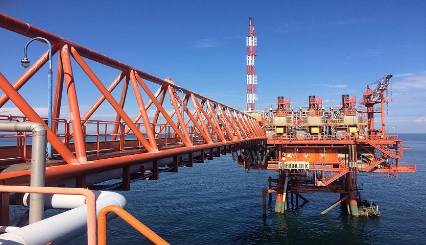
The gas produced at low pressure from Agostino/Garibaldi fields reaches the Garibaldi K compression platform via an 18" line laid on the bridge connecting between Garibaldi C and Garibaldi K platforms.
The gas is conveyed to the slug catcher (VQ-001) to remove and separate any residual liquids. Similarly, the gas which comes from the Ivana field, but only in certain periods of the year, is conveyed into the VQ-002 slug catcher for the liquid separation.
The production of the two fields is combined in a single manifold equally distributed between the compressors (KA-001/002/003) The type of compressor is single-stage centrifugal, driven by a gas turbine.
The gas before reaching the suction flanges of the compressors, the gas passes through the respective VG-001/002/003 suction KO drums which break down the smallest drops of liquids that may be entrained.
The necessary quantity of gas is drawn from the delivery manifold of the gas turbochargers to:
- Supply the Gas turbines 360-MT-001/002/003
- Supply the gas motor generators (of the 470-MG-001 generator sets A/B/C).
The oil tanks of the turbo compressor vent to the air through vents equipped with a blast chiller.
The compressed gas is cooled in the HC-001/002/003 air coolers and then in the HA-001/002/003 shell and tube exchangers with seawater, and then sent to the ground via a pipeline to the Casalborsetti plant passing through the platform Garibaldi T.
Gas receives and separation
The gas arriving on the Garibaldi K platform is separated from the liquid phase before entering the compressors.
The separators exploit the physical process of settling liquids, for the consequent decrease in speed due to the increase in the section of the separator compared to the gas arrival pipeline.
The different specific weight of liquids compared to gas completes the separation process. The liquids separated are sent via a specific pipeline to Garibaldi C, where are located the liquid treatment plant.
Compression gas
This system consists of 3 identical compression lines operating in parallel. The incoming gas is sent to the KO drum suction unit, where the residual liquid is knocked down. Subsequently, the gas is sucked by the single-stage of the gas compressors and compressed it until reaches the pressure necessary for introduction it flows in the sealine and then to Casalborsetti.
Subsequently, the gas is sucked by the single-stage of the gas compressors and compressed it until reaches the pressure necessary for introduction into the sealine and then to Casalborsetti.
The centrifugal compressors are driven by three SOLAR CENTAUR 50-5802 MT-001/002/003 simple cycle gas turbines.
Gas exhaust system
The system is created to collect all continuous or emergency gaseous discharges to convey them and disperse them into the atmosphere through the Emergency Blowdown. The system is composed of a single structure, as demonstrated below:
- High-pressure Blowdown (or Flare), all the lines which collect the high-pressure discharges, safety valves, and the blowdown valve (depressurization valves).
- Low-pressure blowdown (or flare), which collects and burns the continuous gaseous exhaust from the compressor seal circuit (mechanical seals).
Both blowdowns (high and low pressure) have been calculated for not to exceed in the event of accidental ignition, the maximum radiation on the main deck of 1,500 BTU/sqft h max.
Fuel gas system
The system which is powered by raw gas in production drawn from the delivery manifold gas of the turbocompressors, supplies the gas to the gas turbines of the gas compressors, and the gas to engines of the power generation.
The system consists of an electric heater which raises the temperature of the gas to a value such as to prevent (with adequate safety margins), ice formation (hydrates) during pressure-reducing from control valves. Is available also a suitable separator allows the separation of liquids even in the absence of heating.
Instrument air system
The air compression unit consists of two alternative electric compressors (one duty and one in stand-by) in skid mounted version which include refrigerant, storage lung, filtration and drying system. The system can supply oil-free and dehumidified air in the pressure range required by the users.
Sea water cooling system
The sea water is taken from a 15 m depth, filtered and then sent to the shell and tube exchangers to cool the compressed gas. The water coming out of the exchangers is discharged into the sea.
Production capacity
The production capacity of the Garibaldi K platform is 6,000,000 Sm3/d. The maximum compression potential of the platform is 7,450,000 Sm3/g (7,062,000 Nm3/g).
Conclusion
Camp Garibaldi was a great work experience for us and launched us onto much bigger projects. Understanding how these platforms work is of fundamental importance for those who decide to work in the Oil & Gas Industry.
The platforms are always demonised, and seen as structures dangerous for the environment. New studies reveal that they can have a positive impact on the lives of many marine species.

+(39) 347 051 5328
Italy - Kazakhstan


09.00am to 18.00pm
About
We offer the best and economical solutions, backed by 27+ years of experience and international standards knowledge, echnological changes, and industrial systems.
Our Services
Marketing Materials


Marketing Materials1


