
|
LNG (Liquid Natural Gas) nature, composition and characteristics
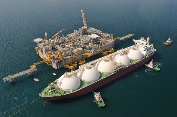
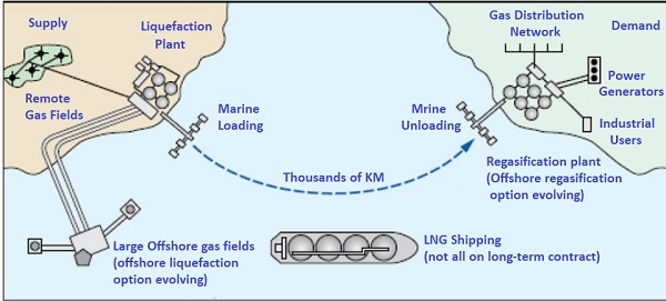
Natural gas has remained the fastest-growing energy resource in most world regions for more than two decades, driven by low greenhouse gas emissions and high conversion efficiency. Natural gas has been transported safely, reliably, and economically for nearly a century via pipeline. The pipelines proved ideal for the supply and market conditions of the twentieth century, using large reserves of conventional natural gas in easily accessible areas. Pipelines have provided stability and security of supply and continue to do so where there are significant gas reserves. However, in recent decades the location of new gas reserves (substantial amounts) is available not in economically viable areas. The focus has shifted to gas reserves previously deemed too remote or technically too difficult and expensive to use. Today, LNG supply chains have diversified and introduced competition into markets once "captured" by traditional gas pipelines and have improved the security of energy supply for many consuming nations and reduced geopolitical and political constraints on global gas supply. A basic understanding of LNG must begin with examining its chemical and physical properties, which is a prerequisite for accurately assessing LNG's potential hazards and safety. The properties of LNG vary with its composition, which depends on the original gas reserve and its processing/fractionation history. Although LNG is predominantly methane (about 87% to 99% by mole), its composition also includes other more noble hydrocarbons, typically C2 to C4 and heavier, nitrogen and traces of sulfur (less than 4 ppmv) and CO2 (50 ppmv). At normal atmospheric pressure, LNG is an odourless, colourless, non-corrosive cryogenic liquid. When LNG is vaporised and used as a fuel for natural gas, it generates very low particle emissions and significantly lower carbon emissions than other hydrocarbon fuels. The combustion products of LNG contain only traces of sulfur oxides and a low level of nitrogen oxides, which makes LNG a clean energy source. LNG is non-toxic. However, the LNG release in the atmosphere (natural gas) can cause asphyxia for the personnel due to a lack of oxygen in an unventilated area. Consider can also be ignited if mixed with the correct air concentrations. The boiling point of LNG varies with its composition, typically –162 ° C (–259 F). The density of LNG generally falls between 430 kg / m3 and 470 kg / m3, which is less than half of the density of water. When poured over water, LNG floats to the surface and vaporiser quickly because it is lighter than water. LNG vapours are initially heavier than air and remain close to ground level. However, once the vapours start to heat by their surroundings and reach a temperature around –166 F, their density becomes less than air, and the vapours float. Vapours released from LNG, if not contained, will mix with the surrounding air and be carried downwind, which can create a vapour cloud that can become flammable and explosive. The flammability limits are 5 percent and 15 percent by volume in air. Outside this range, the methane/air mixture is not flammable ( for more details, click here) The mixture cannot burn when the fuel concentration exceeds the upper flammability limit. The combination cannot burn because the oxygen is too low. This situation exists, for example, in a closed and safe tank where the vapour concentration is about 100 percent methane. The mixture cannot burn when the fuel concentration is below the lower flammability limit. The combination cannot burn because too low methane is present. An example is the loss of small quantities of LNG in a well-ventilated area. In this situation, the LNG vapour will mix rapidly with the air, reaching a concentration of less than 5 percent. Vaporised LNG has the same thermal characteristics as natural gas. Natural gas burns with a low laminar combustion rate in well-ventilated areas and has high ignition energy compared to other hydrocarbon fuels. Natural gas vapour in open areas has never produced unconfined vapour cloud explosions (UVCEs), which are more frequent with other hydrocarbons. The trigger of an explosion depends on multiple factors: the chemical structure of the vapour molecules, size and concentration of the vapour cloud, and intensity of the ignition source, the degree of confinement of the vapour cloud. The conditions necessary to produce the explosion of an unconfined vapour cloud of natural gas are generally not present in an LNG facility, so such explosions should not be considered potential hazards. Supply Chain Energy companies need to invest in many highly connected and dependent facilities to make LNG available for use in a country. The main components of the traditional LNG supply chain, including piping connections between phases, are shown in Figure 1.
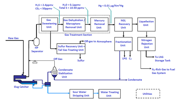
Production plant Figure 2 shows a typical schematic for an LNG production plant designed to produce LNG from an acid gas feeder. The plant's design and requirements depend on the site's conditions, the needs of the supply gas, the compositions, and the specifications of the products.
For more details, we recommend the articles below
Feed gas treatment In a typical scheme, the natural gas, upon its arrival, is treated inside a separator, which removes liquids and directs the gas to a second high pressure (HP) separator. Liquids are fractionated in the stabiliser, producing a lower condensate consisting of C5 and heavier hydrocarbons. The condensate is steam stripped to remove its H2S content and must meet a Reid Vapor Pressure (RVP) specification of 12 psia of pressure required for transportation and storage. The vapours from the intermediate separator and stabilising column are compressed and returned to the HP separator. The vapours then flow to the gas softening unit, GSU (also called the sour gas removal unit, AGRU), where the gas (methane) will separate from H2S and CO2. In particular, H2S is removed from an amino solvent to satisfy the specifications of the total sulfur product, generally 4 ppmv. CO2 is removed at 50 ppmv to avoid freezing in the primary exchangers of the liquefaction plant. Carbonyl sulphide (COS) and mercaptans (R-SH), constituting sulfur contaminants, must also be removed. The acid gas from the regeneration section is sent to the sulfur recovery unit (SRU), typically consisting of a Claus unit and a tail gas treatment unit (TGTU). The off-gas from the TGTU absorber will incinerate. The GSU sweet gas must dry in a dehydration unit by utilising molecular sieves below 0.1 ppmv to avoid hydrate formation in the LNG recovery unit. Usually, the sweet gas is water-saturated, which can be significant in hot weather conditions. It is more energy-efficient and cost-effective to cool the sweet gas by removing most of the water before passing it to the molecular sieve units. The molecular sieve can also design to remove mercaptans from the dried gas to satisfy sulfur specifications. Typically, there are traces of mercury in the feed gas, which must eliminate with removal beds of less than 10 nanograms per cubic meter to avoid corrosion of the mercury downstream of the cryogenic exchanger. Liquefaction The gas exiting the NGL recovery unit enters the liquefaction unit, which cools and liquefies the gas in a refrigeration process. The base of liquefaction technology is on the principle of a refrigeration cycle, where a refrigerant, by subsequent expansion and compression, removes heat from the gas flow, returning it to the ambient air or cooling water. The refrigerant can be part of the natural gas supply process (open loop process) or a separate fluid continuously recirculated through the liquefier (closed-loop process). After liquefaction of natural gas, if the nitrogen content is higher than the commercial specification of LNG, typically 1% by mol, a nitrogen removal unit is required. The low nitrogen content in the LNG product is necessary to avoid low liquefaction temperatures. Reducing the nitrogen content in boiling means it can be used as fuel gas and reduce the risk of storage tank rollover in the terminals. Rollover occurs when there is a rapid mixing of layered layers within an LNG tank which causes the sudden release of very high levels of boiling gas in a short time (A critical phase not to be underestimated). Typically, the LNG coming from the liquefaction plant and compressed to the storage pressure, and the nitrogen, being the lightest component, is eliminated and removed. Nitrogen-rich vapours are compressed and recovered as fuel gas. For transportation, the liquid is pushed into storage tanks by the pump. Suitable for feeding gases up to 2% nitrogen content by moles. However, the simple end-flash process is insufficient with a high nitrogen feed gas, and an additional fractionation step is required. If not removed, the high nitrogen content would reduce the liquefaction temperature and increase the energy consumption of the refrigeration unit. In addition, the nitrogen content of the flash gas and the boiling gas would be higher, which may not meet the specification of the calorific value of the fuel gas. Removing nitrogen by the cryogenic separation process is the process par excellence for LNG production. Other alternatives, such as adsorption or membrane technology, are not economically competitive for meeting the very low nitrogen specifications (Finn, 2007; Garcel, 2008). For more details, we recommend the articles below
Loading of LNG Depending on the customer's request, LNG can be loaded into LNG trucks in a truck loading area and/or onto LNG ships on docks. To load LNG to a truck or ship, are used cargo pumps. For the high cost of ship parking, the LNG loading and unload phase must be as short as possible. Depending on loading speed and loading arm capacities, two or three liquid loading arms are required. The loading lines are kept refrigerated during the operation and even in the absence of loading activity. During no load activity, a small flow of the LNG of the plant is circulated towards the head of the pier and back to the storage tanks continuously. Operation is necessary to keep the loading system cold and free of gas to avoid thermal stress and allow an immediate start of loading the ship after an LNG carrier's arrival. An additional arm to manage gas vapours from the ship's tank and boiling gas (BOG). Note that the choice of thermally insulating the pipeline from storage to the ship can minimise heat transfer to the pipeline and BOG formation. Regarding mechanical Insulation, the most commonly used materials are glass foam and polyisocyanurate “powder” insulation such as airgel, perlite, izoflex, and high vacuum insulation. For more details, we recommend the articles below
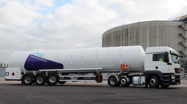
LNG transportation The next step in the LNG supply chain is the transportation of liquefied natural gas to the regasification facilities. The main modes of transport are by ship and truck. Il GNL è trasportato da navi specializzate, con serbatoi isolati a doppio scafo, progettati per contenere il carico leggermente al di sopra della pressione atmosferica a una temperatura criogenica di circa –169 °C. Typically, storage tanks operate at 0.3 barg with a design pressure of 0.7 barg. The tank design ensures the integrity of the hull system and provides insulation for LNG storage. Since the insulation cannot prevent all external heat from reaching the LNG, some of the liquid will vaporise during the journey. LNG vaporisation is not homogeneous: components with the lowest boiling point (nitrogen and methane) evaporate more quickly than heavier components. This phenomenon is called ageing, and its consequence is that the composition of LNG becomes heavier, and the warming value and Wobbe index of LNG increase over time. Boiling gas, typically around 0.10% to 0.15% of the ship's volume per day, in this case, must be removed to keep the ship's tanks at constant pressure. Depending on the ship's design, the boiling gas can be used as fuel in the ship's dual-fuel engines or burned in boilers to produce steam or regenerated and returned to cargo tanks. If the consumers' location is near coastal areas, it's possible to deliver the LNG by ship. Different story if far from the coast, the only viable method is trucking with mobile equipment such as road trailers (Figure 3), ISO cryogenic containers or smaller delivery units.
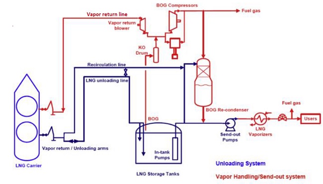
On the production side, the liquefaction of small scattered sources of natural gas or biogas in remote areas would not be economically feasible if not placed close to consumption. On the other hand, the capacity of the tank and its useful life may not justify the construction of long pipelines and liquefaction. In these cases, the transport of LNG trucks presents an economically viable solution. On the consumer side, the price of natural gas remains historically low due to the rapid development of shale gas in North America, which makes natural gas a clean, low-cost fuel. LNG trucking is now a mature industry. Liquefied natural gas can be reliably and safely delivered to LNG filling stations using specialised double-walled tankers with vacuum insulation. At satellite stations, the LNG is unloading into insulated pressurised storage tanks. Under normal conditions, the vacuum insulated tank can store LNG for long periods without venting. LNG is pumped, vaporised with ambient air vaporisers for domestic gas consumers, odorised, measured, and delivered to local pipelines. Commercial truck fleet operators are progressively resorting to converting vehicles to natural gas. For more details, we recommend the articles below LNG receiving terminals LNG carriers deliver LNG to a receiving terminal, returning the LNG to a gaseous state. Natural gas is delivered to users using distribution pipelines. Historically, onshore LNG terminals have been close to populated and industrial areas. Figure 4 shows a typical process diagram of the ground-based LNG receiving terminal. As can be seen from Figure 4, the LNG is unloaded using the ship's pumps to the unloading arms on the dock and then to the storage tank via the unloading lines. Next, pumped at high pressure through various components and heated in a controlled environment. Existing several methods for heating the LNG, all described below:
Once regasified, the natural gas will deliver to the different uses or power generation stations in the distribution pipelines. For more details, we recommend the articles below LNG regasification Choosing a correct LNG vaporisation system depends on the factors below:
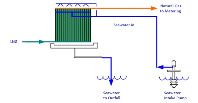
It must also meet industry requirements regarding the minimisation of operating costs. System selection is based on economic analysis to maximise project NPV and meet emissions requirements. Large regasification terminals use two types of vaporisers: Open Rack Vaporizator (ORV) and Submerged Combustion Vaporizer (SCV).In addition to these vaporisers mentioned above, several other types have been used, and are Ambient Air Vaporizers (AAV), Shell and Tube Exchange Vaporizers (STV) and Intermediate Fluid Vaporizers (IFV). Vaporiser selection is project-specific and site-specific and must be evaluated case-by-case. Open Rack Vaporizer is the heat exchanger that uses water as a heat source. The water source for these units depends on the terminal's location and the amount of water available. LNG receiving terminals generally are located near the open sea. Therefore, seawater is the most commonly used source of heat. Generally, the build of this unit is in aluminium alloy finned tubes, which provide LNG's low-temperature mechanical strength. The mechanical construction of these units is simple. The pipes arranged are in panels, connected through the LNG inlet and the regasified product outlet pipes manifolds and hung on a rack. This function allows easy access to the exchanger for maintenance purposes.
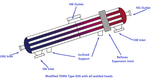
Maintenance of these units is simple, as there are no moving parts. The team can be started or stopped from a remote control station without the physical intervention of an operator. However, maintenance is more frequent than in other vaporisers since the tubes need to cleaning regularly. On these units, the load operating can regulate by varying the amount of seawater flow and/or the flow of LNG through the pipes. Depending on the unit's design, it is possible to isolate sections of the panels and vary the load on the units. These units are reliable and have excellent safety records. The gas leak can be quickly detected and can safely shut the unit. There is no danger of explosion because there is no ignition source in the system. Tube bundle vaporisers (STVs) are composed in an open-loop, closed-loop, or combined mode. The open-loop configuration means that a pump sends seawater to vaporise the LNG. STV works similarly to the ORV, except for seawater. Seawater goes through the shell and tube exchangers (use pump anyway). The construction of the exchanger shell is stainless steel and high-pressure, while the exchanger tube is in titanium or other materials suitable for seawater operation. The cost of materials for STV exchangers is high, but the dimensions are relatively compact.
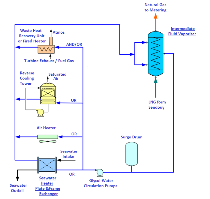
The Interposed Fluid Vaporizer (IFV) uses an interposed fluid to perform heat exchange (HTF) in a closed-loop to transfer heat from a heat source to the LNG vaporisers. The interposed fluid can be ethylene glycol or propylene glycol. Other low freezing heat transfer fluids are suitable for operating temperatures. The heat transfer for the vaporisation of LNG takes place in a tube bundle exchanger. For more details, we recommend the articles below Conclusion However, classifications of the LNG plants and LNG ships are high-risk activities. Personnel working on these plants are trained, including knowledge of the operating principles of the entire plant. Suppose something goes wrong during an LNG carrier's loading or unloading phase. In that case, these enormous quantities of cubic meters multiplied by 600 times become a devastating thing for the entire plant and those who work there. In terms of safety, this system is super controlled. All equipment such as valves or sensors that detect the presence of gas must be inspected rigorously and tested periodically to avoid any accident that could be fatal at any moment. We know the whole plant perfectly. The most critical phase of the LNG transfer is the Flexible cryogenic tubes connections. There are procedures to be respected, as written in the dedicated article. For more details on security systems, click here.
|


+(39) 347 051 5328
Italy - Kazakhstan


09.00am to 18.00pm
About
We offer the best and economical solutions, backed by 27+ years of experience and international standards knowledge, echnological changes, and industrial systems.
Our Services
Marketing Materials


Marketing Materials1


