


What Makes
us Special?
0
Sucessful Projects
0
Satisfied Clients
0
Awards Won

Peripheral Interface Microcontroller, PIC microcontrollers, came to the form in 1993. Initially, they were designed and developed to support PDP computers to control peripheral devices. PIC microcontrollers are fast and easy microcontrollers for executing programs in it. It is based on one of the famous architecture, Harvard architecture.
Besides, the ease of programming, interfacing, wide availability, lower cost, serial programming capability, and more extensive user base are the reasons that make these PIC microcontrollers popular.
This article briefly explains the PIC microcontroller, which requires consideration before choosing a PIC microcontroller. Additionally, it also listed the top 20 PIC microcontrollers that can be found in the market.
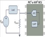
The microcontroller is an integrated chip mainly consisting of CPU, RAM, timer, ROM, counter, etc. Similarly, the PIC microcontrollers have a similar architecture that supports the UART, SPI, and CAN interfaces with other peripherals.
The 8-bit PIC microcontrollers are further classified into four types based on the internal architecture: mid-range PIC, baseline PIC, PIC18, and enhanced mid-range PIC. It is controlled by the software and programmed in a way that could perform the task.
Currently, PIC microcontrollers have broad applications for industrial purposes because of low power consumption, ease of supporting software and hardware tools like debuggers, simulators, and compilers, high-performance ability, etc. Also, they are really cheap and easily programmable or assembled by the users.
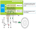
The PIC microcontroller architecture consists of an I/O port, CPU, A/D converter, timer, memory organization, interrupts, oscillator, CCP module, and serial communication.
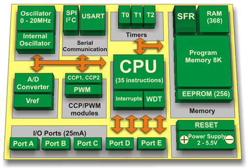
Like other microcontrollers, the CPU of the PIC microcontroller also consists of ALU, CU, accumulator, and MU. At first, ALU mainly makes logical decisions and is used for arithmetic operations. Similarly, the instructions are stored in memory after processing. Then the control unit connects to the CPU and thus controls the internal and external peripherals.
The accumulator also stores the results and processes further.
Data Memory and Program Memory are the two memories used in PIC microcontroller architecture.
Program Memory stores the 13 bits of program code. The program counter registers access to the program memory data. Similarly, the data memory consists of RAM and EEPROM. They consist of multiple banks with a particular function register and a general purpose register.
It consists of five ports Port A, Port B, Port C, D, and E. Port A is a 16-bit port that can be used as an input and output port. The TRISA register determines this decision. Likewise, Port B is the 8-bit port that can be used as an input and output port. Moreover, Port C is similar to that port B, whose operation is determined by the TRISC register. While Port D is an 8-bit port that acts as a slave port for connecting to the microprocessor bus. Finally, Port E is the 3-bit port that controls the signal to the A/D converter.
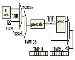
PIC microcontrollers consist of 3 timers, out of which timers 0 and 2 are 8 bits and timer 1 is 16 bits, which also works as a counter.
PIC microcontrollers consist of a 10-bit ADC. Further, this unique function registers to control the operation. The lower and upper bits of the register and divided and stored among these two registers. This converter requires an analog reference voltage of 5V.
It controls the timing of the microcontroller. It consists of an external crystal oscillator that determines the range of clock frequency for the microcontroller.
Serial Communication Protocol is the method of transferring data over the communication channel. USART, I2C, AND SPI are the three protocols used in PIC microcontrollers. The USART protocol is used for transceiving the connection to the clock pulses. SPI protocol sends the data between the PIC microcontrollers and other peripherals or external devices. Similarly, the I2C protocol is used for connecting low-speed devices.
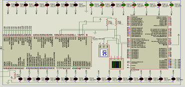
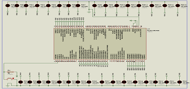
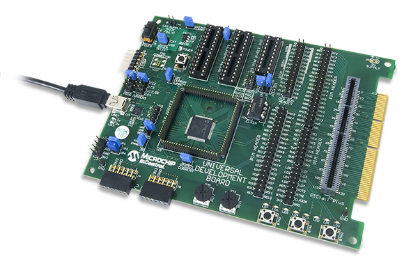
The Universal Development Board (UDB) is a microcontroller development board intended to use with a wide variety of PIC microcontrollers from Microchip®. It was designed to support most 3.3V, PIC microcontrollers in 8-bit, 16-bit, or 32-bit varieties. It will accommodate a wide range of Microchip PIM processor modules as well as DIP packaged parts with pin counts from 8-pin to 28-pin. Three DIP sockets are provided: 20/14/8 PIN 8-bit PIC, 28 PIN 8-bit PIC, and 28-pin PIC24/dsPIC33/PIC32MX. This board also has discrete I/O elements and 2 Pmod ports for further device evaluation or product development capability. Expansion connectors are provided that are compatible with the Microchip PICtail™ Plus line of expansion modules. In addition to the PIM connector and DIP sockets, a PIC32MX360 microcontroller is also provided for use without the need for additional PIM or DIP socketed processors. The Universal Development Board is designed to be compatible with the Microchip Explorer 16 development board. The layout of the PIM connector and PICtail™ Plus bus connections are physically and electrically compatible with the Explorer 16, and many Microchip demonstration programs for the Explorer 16 will work with the UDB.
The Universal Development Board is designed to be compatible with the Microchip Explorer 16 development board. The layout of the PIM connector and PICtail™ Plus bus connections are physically and electrically compatible with the Explorer 16, and many Microchip demonstration programs for the Explorer 16 will work with the UDB.
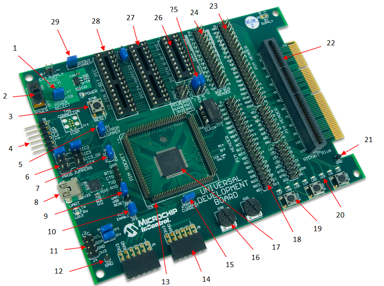
| Call Out | Function | Call Out | Function |
|---|---|---|---|
| 1 | J21 Power Select Jumper | 16 | Potentiometer |
| 2 | Power Switch | 17 | PIC32 Microcontroller MX360 |
| 3 | Reset Button | 18 | PIM Header |
| 4 | In Circuit Serial Program Connector | 19 | User I/O Buttons |
| 5 | SPI EPROM Enable | 20 | User I/O LEDs |
| 6 | Programming Jumpers | 21 | GND Reference |
| 7 | PIC32 Current | 22 | PICtail Plus Connector |
| 8 | USB Serial Converter | 23 | PIM header |
| 9 | USB UART Reset | 24 | DIP header |
| 10 | PIC32 Enable | 25 | Programming Jumpers |
| 11 | I2C Connector | 26 | 10/14/8 8 Bit PIC |
| 12 | GND Reference | 27 | 28 Pin Pic 24/ dsPIC33/ PIC32 |
| 13 | PIM Socket | 28 | 28 Pin 8 BIT PIC |
| 14 | Pmod port | 29 | DIP current measurement |
| 15 | PIM current measurement jumper |
Power Supply
The UDB can be powered in one of two ways, either by a bench supply or a wall wart type power supply attached to the power header, J20; or from the USB connector, J23, associated with the USB serial converter. The UDB is intended to be operated from a regulated 5V power source, however with certain restrictions, a different supply voltage can be used. The absolute maximum voltage that should be applied to the power header is 6V.
If an external power source other than a regulated 5V supply is used, the voltage on the VCC5V0 bus will be the voltage of the external supply, and the test points on the board labeled 5V will actually be at the voltage of the external supply.
USB Power
To power the board with from the USB use a USB 2.0 A to Mini B cable to connect the PC to the UDB via connector J23. The Jumper at J21 (power select) must be placed in the USB position and the power switch, SW1, must be in the ON position. When the board is powered, the LED at LD8 will be illuminated.
External Power Supply
To power the board using an external power supply connected to J20 (EXT Supply 5VDC), the jumper at J21 (Power Select) must be placed on the EXT position. In order for the board to be powered the switch at SW1 must be in the ON position, when the board is powered, the LED at LD8 will illuminate. If SW1 is in the OFF position the UDB is not powered. A fail to power can also occur if the jumper at J21 is in the USB position.
Connector J20 is a two pin header using 100mil spaced, 0.25mil square posts. An MTE style connector or clip leads can be used to supply power to this header. The proper polarity is marked on the board. A Shotkey diode, D5, is provided for reverse polarity protection.
Power Supply Circuit Description
All on-board circuits operate at 3.3V. The primary regulated power bus VCC3V3 is powered by a voltage regulator circuit made up of IC9, a Microchip MCP1703 LDO voltage regulator and the associated input and output capacitors C32, C33 and C34. This regulator is rated for a maximum dropout of 625mV. To ensure that the regulator output is the proper 3.3V, the minimum voltage applied to the input of the regulator should be 4V. Allowing for the forward drop across the reverse polarity protection diode, D5, in the input circuit, the minimum external supply voltage should be 4.4V.
In addition to the main voltage regulator, a second regulator is used to provide power to the USB serial converter circuit. This regulator is made up of IC11, a Microchip TC1014 LDO voltage regulator and the associated input and output capacitors C28 and C29 and bypass capacitor C30. This regulator is always powered from the USB connector J23, and therefore, power is only supplied to the USB serial converter when J23 is connected to a live USB port.
9V0 Power Supply for PIM/PICtail Plus Bus
Some Microchip PICtail™ Plus modules require a 9V power supply to power some of their functions. There is no 9V power supply on the UDB board. If a PICtail™ Plus module is being used that requires the 9V power supply, an external, regulated 9V supply can be attached at J5 to provide this voltage. Jumper J5 is an unloaded, two pin header in the upper right corner of the board. Note the polarity marking on the board as it is not internally protected from reverse polarity.
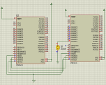
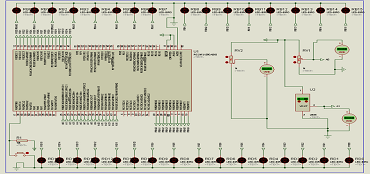
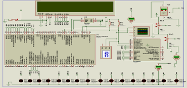
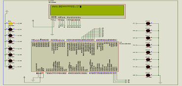
A Microcontroller can be defined as the integration of microprocessor and other required external components onto a single microchip and optimized to interact with the outside world through on-board interfaces. Latest microcontroller comprises of a microprocessor module, ROM (Read Only Memory) module, RAM (Random Access Memory) module, I/O (Input Output functions) modules, and various other specialized circuits all in one package.The PIC development board are used in automatically controlled products.
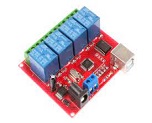
This PIC development board offers RS232 (Receiver, Transmitter including RTS, CTS), USB port, a switch, LED modules, ICSP devices, a reset and power monitoring buttons, I2C device, external / USB power supply, to stabilize the system’s power, connector for alternate power battery and power switch and an expansion bus.
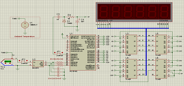
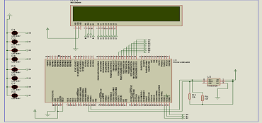
A PIC 32 microcontroller universal board is a powerful development platform based on PIC18F452 microcontroller, PIC18F252 microcontroller, PIC16F877A microcontroller and PIC16F84 microcontroller. PIC 32 USB based data logging, application in real time data monitoring and control process, interactive control panel systems, etc. The 32 series microcontrollers are really fast, they use the MIPS system (Million Instructions per Second).
On-chip USB controller provides a direct high-speed interface to a PC/ laptop with speeds up to 12Mb/s speed. The UART boot loader eliminates need of an additional programmer and allows you to program using serial port interface. The onboard peripherals include a USB interface port, ULN2003 current sinking driver interface, L293D DC motor controller for devices, 16X2 character LCD.
The on chip peripherals and the external hardware on the development board are interconnected using pin headers and jumpers in a board. The I/O pins on the microcontroller can be accessed easily. The board is made from double sided PTH PCB board to provide extra strength to the connector joints for increased reliability application. PIC develoment board supports the operating supply voltage between 5V DC and 12 V AC and has built-in reverse polarity protection. For more details, you can download the PIC 32 manual here. For more details see the PIC32 series development boards below because they are very interesting.
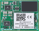
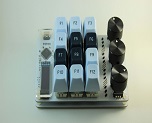
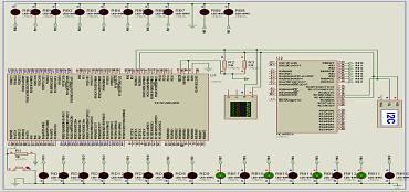
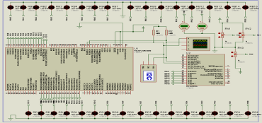
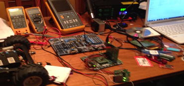
The SnadPIC is a microcontroller board based on the Microchip PIC32, PIC24 and dsPIC families. It is designed to be easy to use and suitable for use by anyone from beginners to advanced users for experimenting with electronics and embedded control systems. It contains everything needed to start developing embedded applications.
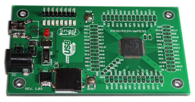
It is designed to provide a low cost small control solution. It is intended to introduce and
demonstrate the capabilities and features of PIC32, PIC24 and dsPIC with on- chip USB OTG. The board also comes with all the basic components needed for the Microchip PIC32, PIC24 and dsPIC families, so you can use it straight out of the box. Except for a single connection to a computer, no additional hardware or configuration is
necessary. A USB connection to a host computer supplies communications and power to the board. For independent host-side USB operation, the starter kit may be disconnected from the PC and powered through DC Power Jack for independent functionality. The starter kit provides 83 I/O pins that support a number of peripheral functions, such as UART, SPI and I2C™ ports and pulse width modulated outputs. Use of these advanced peripherals requires an add on board to provide the additional hardware required.
Through the USB interface, it can also be programmed without the need of a programmer, as there is a built in Microchip boot loader.
The starter kit can be powered via USB, an external DC power adapter, or batteries.
Features
|
|
File attached below
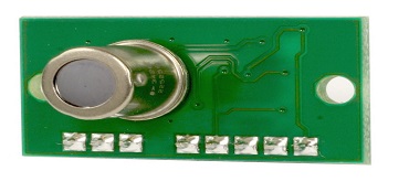
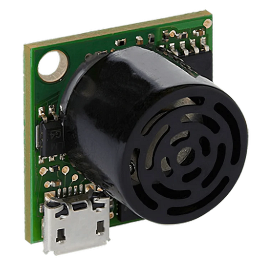
In an electronic circuit, there are different components, including resistors, capacitors, inductors, diodes, transistors, ICs, connectors, etc. Each of these components performs in a specific way so the desired output of the circuit board is achieved.
A circuit board, also known as a printed circuit board (PCB), is a fundamental component in electronics. It’s the backbone of most electronic devices, providing a platform for the arrangement and interconnection of electronic components.
Circuit boards are found in nearly every electronic device, from simple devices like digital watches and calculators to complex devices like computers and televisions. They are designed to route electric signals through electronics, which allows the device to function as intended.
While circuit boards can be made manually via soldering techniques, professional circuit boards are made with printing technology, hence their name, Printed Circuit Boards (PCBs).
Since circuit boards allow electronic components to interact and work together, they enable the device's functionality. Without circuit boards, modern electronics as we know them would not exist.
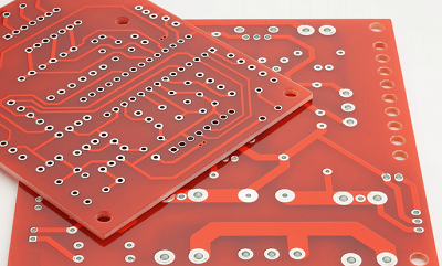
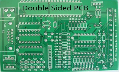
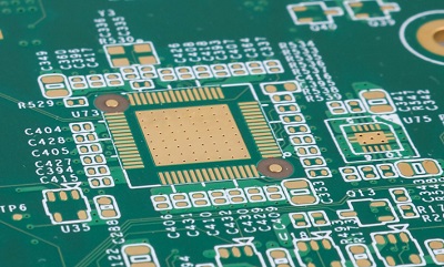
Typically, circuit boards are made from an insulating material, often fibreglass (double or single-sided, or even multi-layered), and are coated with conductive materials. These conductive materials, usually copper, are etched to form pathways that electric currents can follow. These pathways, known as traces, connect the various components on the board, such as resistors, capacitors, and transistors, allowing them to work together to perform complex tasks.
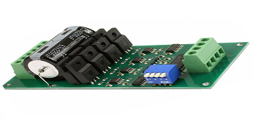
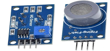
So, a circuit board combines semiconductors, insulators, and conducting materials to achieve a specific objective. i complessi. Figure below shows different types of circuit boards
|
|
|
|
There are many special features that are designed into the printed circuit board (PCB) that will increase the number of processing steps that it takes to complete the order. The combination of features can add additional cost to the raw PCB and increase the lead time to process.
When considering a PCB design and layout or redesign, it would be advantageous to consult with experts. Your printed circuit board supplier should have engineering resources to consult and review preliminary information and be able to assist with design suggestions.
Why High-Tech Multi-Layer PCB Features Add Cost and Processing Time
In this webinar we discuss multilayer features for printed circuit boards that add cost and processing time. We will also look at base costing materials, copper weights, common cost adders, plating finishes, processing, less common features, and more.
Deal With bennypass and
Get More Valuable Services
Microchips can be purchased for various applications through major retailers, with Microchip Technology Inc. offering industrial, automotive, and computing solutions
For Business: For Business inquiry pls fill our feedback form and
Troll Free Number – (+39)347-051-5328.


We offer the best and economical solutions, backed by 27+ years of experience and international standards knowledge, echnological changes, and industrial systems.


