Anti-surge Valve
Functions of an Anti-Surge Valve
The main function of an anti-surge valve is to protect equipment and systems from overpressure and pressure surges that can occur during rapid changes in flow rate. Some of the specific functions of an anti-surge valve include:
- Preventing damage to the equipment: by releasing pressure when the system pressure exceeds a set point, the valve helps to prevent damage to the system and its components.
- Maintaining system stability: by regulating pressure, the valve helps to maintain the system stability and prevent system failure.
- Improving system efficiency: by preventing pressure surges, the valve can improve system efficiency by reducing the amount of energy required to operate the system.
- Reducing noise: by releasing pressure, the valve can also reduce noise in the system caused by pressure surges.
- Minimizing downtime: by protecting the system from overpressure and pressure surges, the valve helps to minimize downtime and reduce maintenance costs.
- Controlling the flow: anti-surge valves can be used to control the flow of fluid or gas in the system.
- Protecting compressors and pumps: anti-surge valves are commonly used in systems that have rapidly changing flow rates, such as in turbocharged engines, compressors, and pumps.
Anti Surge Valve Requirements
Anti-surge valves have several requirements that need to be considered when selecting and installing them in a system:
- Set point: the set point of the valve is the pressure at which the valve will open and release pressure. It is important to select a set point that will protect the system and its components from overpressure and pressure surges.
- Flow rate: the valve must be able to handle the flow rate of the system in order to effectively release pressure. The valve size and type must be selected based on the flow rate of the system.
- Pressure drop: the valve must be able to release pressure without creating a significant pressure drop in the system. The pressure drop must be minimized in order to maintain system efficiency. The design shall be sufficient to handle high-pressure drops if the situation arises.
- Response time: the valve must respond quickly to pressure changes in order to protect the system from overpressure and pressure surges. The response time of the valve must be fast enough to meet the needs of the system.
- Material: the valve material must be compatible with the fluid or gas in the system in order to prevent corrosion or damage to the valve.
- Environment: the valve must be able to withstand the environmental conditions of the system, such as temperature, vibration, and external impacts.
- Control: the valve must be equipped with a control system that can automatically adjust the set point to match the changing conditions of the system or manual adjustments.
- Safety: the valve must be designed and installed in a way that ensures safety for the operators and maintenance personnel.
- Maintenance: the valve must be designed for easy maintenance and repair, to minimize downtime and reduce maintenance costs.
- Cost: the cost of the valve must be considered in relation to the overall cost of the system and the potential savings from preventing damage and downtime.
- Good Stroke Speed: the anti-surge valve must be having good stroke speed
- Size: the valve shall be properly sized to control the surge.
- Valve Construction: To handle extreme service conditions, the construction must be robust.
Typical Design of the Anti-Surge Valve
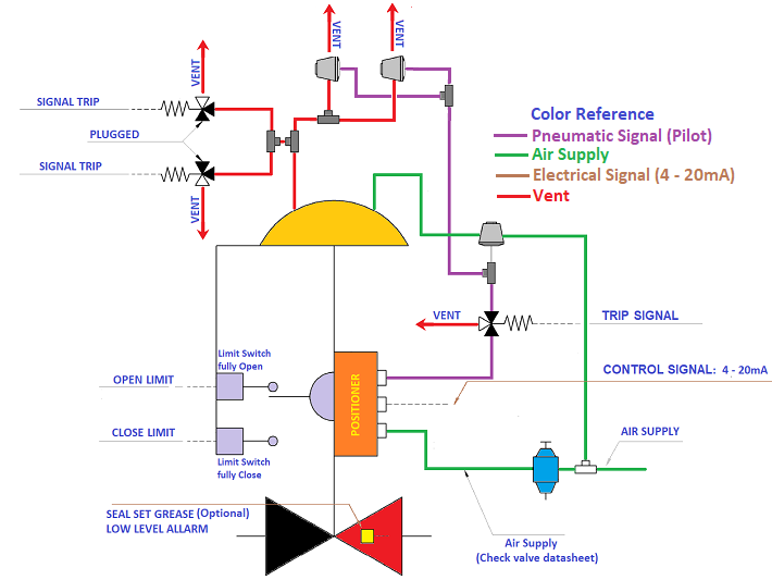 Figure 1 - Typical Design of Anti-surge Valve Figure 1 - Typical Design of Anti-surge Valve
This type of design produced by Pignone, is worthy of this brand name, in fact, in terms of safety it has been studied very well. This configuration has been installed and tested In Iran (Darquain, and Asaluyeh Project) and Kazakhstan (Kashagan and Karashagana Project), and Lybia ( wafa project).
Let's examine the valve point by point:
- The Air Supply and Vent are entirely separate from Actuator. This is most important because in case fail the booster which charges air in the actuator (fail means remains stuck open) the valve any way will open by solenoids to the other side of the actuator. Consider that the vent line where are connected the solenoid is bigger if compared with the supply line. This is something of fundamental importance.
- Two boosters are installed on the vent side, especially in the first stage where pressure or flow can change any time due to process condition
- Since the opening speed of this valve, it is of fundamental importance to protect the compressor, Pignone chooses to install two solenoids in the vent, if one of them fails, the other one anyway will open. Even if it exists a third solenoid which cuts the pilot air to the booster, the priority one is the vent line.
- Volume Booster has been chosen from Fisher which is the best one for Anti-Surge.
- ABB positioners on the actuators are installed, which is not easy to calibrate, but once the position is found (follow the manual), the calibration becomes very simple. This positioner keeps giving errors until it will be configured properly. Another positioner which I recommend is the S.T.I.
- Limit switch full open and close in place to avoid any missing understanding during start-up
- The injection grease chamber inside the body valve which is in auto-mode injects grease on the stem packing thanks to the pressure from upstream of the valve itself.
Positioner Calibration
Recommendation
Qualified personnel Only those persons familiar with the installation, commissioning, operation and maintenance of the TZID positioner or similar instruments who have the required qualification and have read and understood the operating instructions are authorized to work on the TZID positioner. These persons must be sufficiently trained and experienced and know the relevant standards and regulations to be able to judge their assigned tasks and recognize potential hazards. Only persons who are qualified or have been trained adequately and who have the required certificates are authorized to work on explosion-protected devices.
installing and commissioning
Note: No further steps are required if the TZID positioner is delivered mounted on the actuators.
IMPORTANT - These operating instructions describe how to mount the positioner to linear actuators in accordance with DIN/IEC 534 (lateral attachment to NAMUR) and to rotary actuators in accordance with VDI/VDE 3845. Customized positioners for actuator-specific attachments require specific instructions, which are already delivered with the device or can be ordered from us.
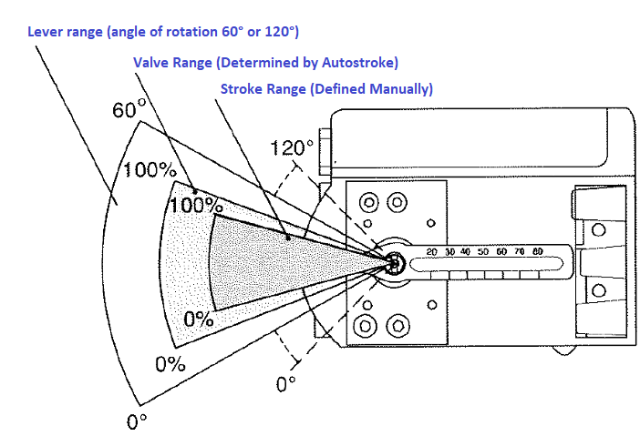 Figure 2 - Mechanical Configuration of Positioner Figure 2 - Mechanical Configuration of Positioner
When mounting the positioner, ensure that the transíer of the stroke or rotation angle for the position feedback is correct.
The maximum rotation angle is 60° for mounting to linear actuators and 120° for mounting to rotary actuators.
Due to the high-resolution A/D conversion (> 8000 steps), no extra adjustment of the used angle of rotation is necessary when mounting the positioner. Fine adjustment is done later in the commissioning phase through electronic configuration (Autostroke).
For safety reasons, the range actually covered by the positioner's angle of rotation should not reach the limits of the total range, but should be greater/smaller than these limits by 2%. While commissioning the positioner, you can determine its angle of rotation by using an electronic parameter.
The actually used angle of rotation should be at least 20 % of the total range. This value can also be determined electronically in the commissioning phase.
Mounting to linear actuators
A mounting kit is available for mounting the positioner to a linear actuator in accordance with DIN/IEC 534. Fig. 3 gives you an overview.
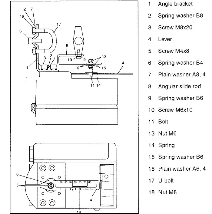 Figure 3 - Mounting kit for linear actuators Figure 3 - Mounting kit for linear actuators
The lever (4, standard version), the screw (5), the spring washer (6) and the spring (14) are included in the positioner delivery. All other items are part of the mounting kit which has to be ordered separately. The TZID positioner ( ABB) comes with the lever (4) already installed. All other items are delivered in a separate package. The lever is available in two lengths: for 10 to 85 mm strokes (standard version) and for strokes 10 to 150 mm (special version, to be ordered separately).
Fasten the angular slide rod (8) to the actuator stem using the screws M6 (10) and spring washers (9).
Actuators ready for attachment in accordance with DIN/IEC 534 have two exactly arranged Threaded holes M6 in the stem.
Fasten the angle bracket to the positions and to the actuator's cast iron yoke or columnar yoke using the screws and spring washers (2, 3). Proceed as shown in Fig. 4 and Fig. 5.
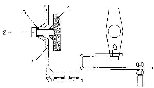 Figure 4 - Mounting the positioner to a cast iron yoke Figure 4 - Mounting the positioner to a cast iron yoke
Fasten the angle bracket (1) with the screw (2) and the plain washer (3) to the cast iron yoke (4)
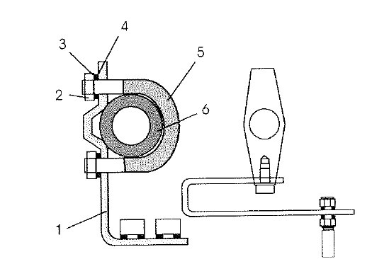 Figure 5 - Mountìng the positioner to a columnar yoke Figure 5 - Mountìng the positioner to a columnar yoke
- Hold the angle bracket (1) in the appropriate position against the columnar yoke (2).
- Insert the U-bolts (5) from the inner side of the columnar yoke through the holes in the angle bracket.
- Slip on the plain washers (3) spring washers (4) and nuts (2) Hand-tighten the nuts evenly.
Important: Adjust the height of the positioner at the cast iron yoke or the columnar yoke until the lever is horizontal (at visual check) at half valve stroke.
Adjusting the stroke
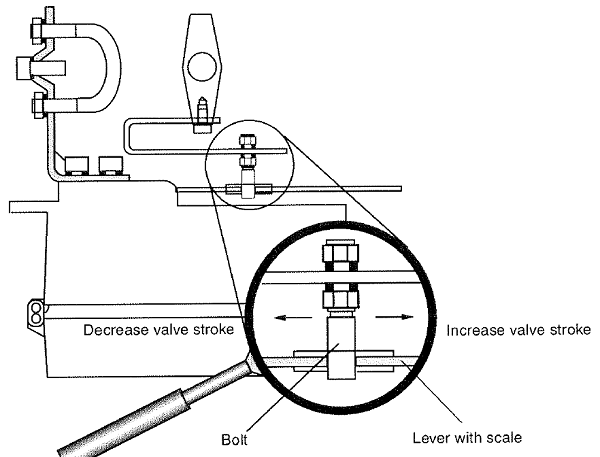 Figure 6 - Positioner linkage Figure 6 - Positioner linkage
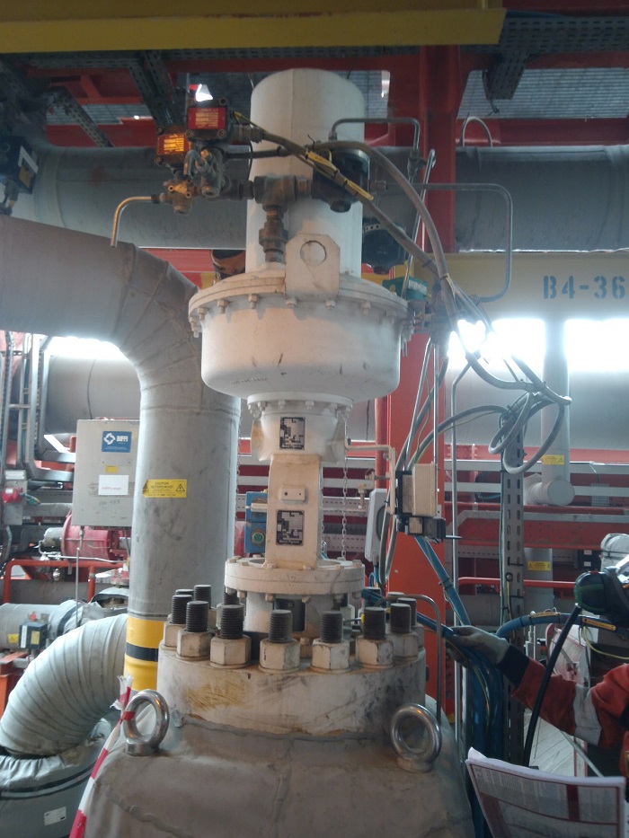 Figure 7 - Typical Connection Figure 7 - Typical Connection
The poisoning travel (stroke) is transmitted to the positioner via the bolt. You can adapt the valve stroke range to the operating range of the position sensor by shifting the bolt in the lever's oblong hole. A scale on the lever helps you to determine the valve stroke range.
Use the lever scale to set the bolt io the appropriate position. A rough adjustment is sufficient. The fine adjustment adjustment will be done later in the commissioning phase using the Auto-stroke function.
|


