Dry Gas Seals for Compressors
Polymer Dry Gas Seal for Low Temperature applications Tmin = -170°C
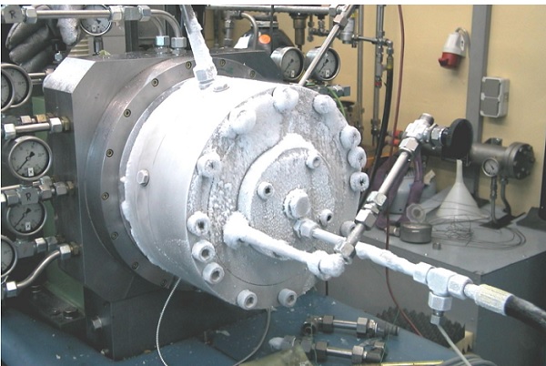 Figure 1 - Dry Gas seal for low temperature Figure 1 - Dry Gas seal for low temperature
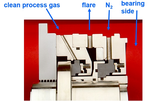 Figure 2 - Tandem Dry Gas Seal with internal labyrinth Figure 2 - Tandem Dry Gas Seal with internal labyrinth
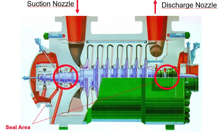 Figure 3 - Centrifugal Compressor Figure 3 - Centrifugal Compressor
Why Dry Gas Seals ?
- No oil usage
- High reliabilty
- High Safety
- Low Maintenance Costs
- Low Operating Costs
- Low Process Gas Losses
- Environmental Concerns
- Operating Simplicity
Dry Gas Seal components
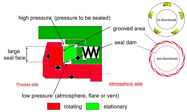 Figure 4 - Dry Gas Seal components Figure 4 - Dry Gas Seal components
Forces
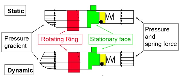 Figure 5 - Forces Figure 5 - Forces
Reaction to transients
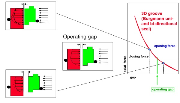 Figure 6 - Reaction to transients Figure 6 - Reaction to transients
uni - directional, V - Groove
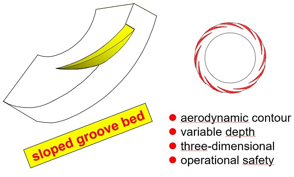 Figure 7 - uni - directional, V - Groove Figure 7 - uni - directional, V - Groove
Dry Gas Seal Principle V-groove
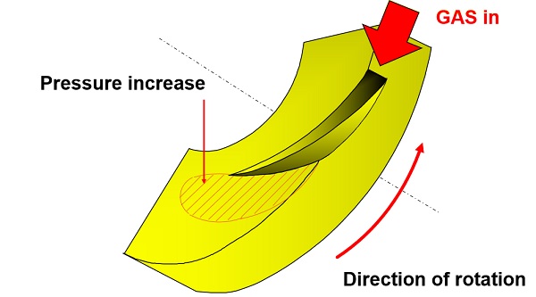 Figure 8 - Dry Gas Seal Principle V-groove Figure 8 - Dry Gas Seal Principle V-groove
bi - directional, U - Groove
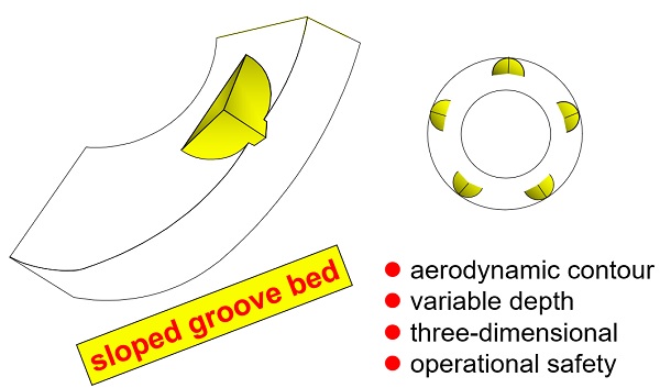 Figure 9 - bi - directional, U - Groove Figure 9 - bi - directional, U - Groove
Dry Gas Seal Principle U-groove
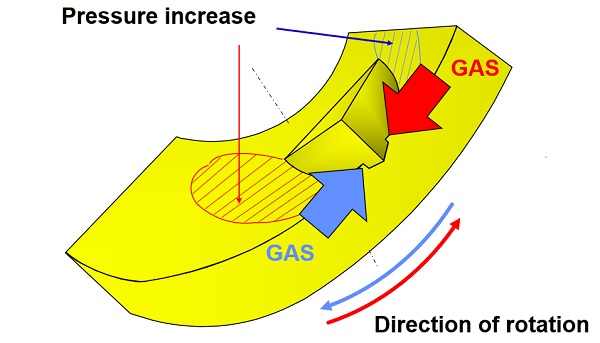 Figure 10 - Dry Gas Seal Principle U-groove Figure 10 - Dry Gas Seal Principle U-groove
Dry Gas Seal Principle U-groove
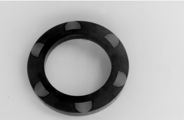 Figure 11 - Dry Gas Seal Principle U-groove Figure 11 - Dry Gas Seal Principle U-groove
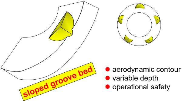
sloped groove bed
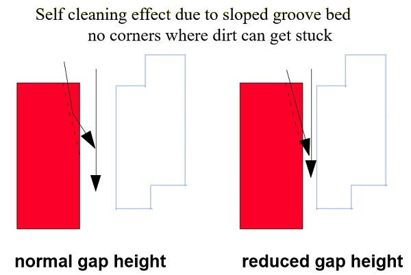 Figure 12 - sloped groove bed Figure 12 - sloped groove bed
Seal face material combinations
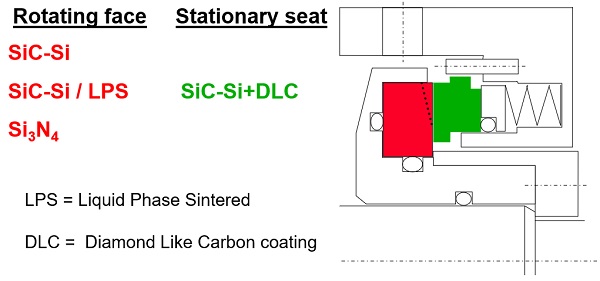 Figure 13 - Seal face material combinations Figure 13 - Seal face material combinations
Seal face characteristics
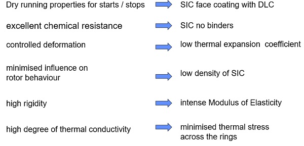 Figure 14 - Seal face characteristics Figure 14 - Seal face characteristics
Dry Gas Seal Arrangements
Single seal arrangement
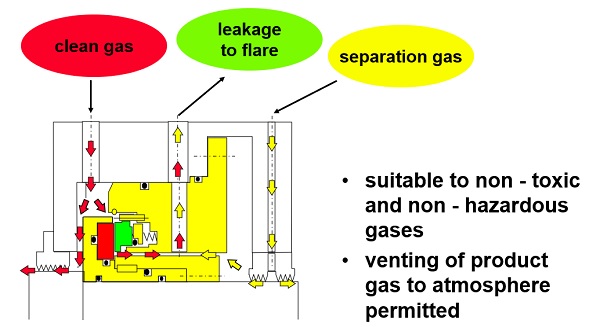 Figure 15 - Single seal arrangement Figure 15 - Single seal arrangement
Tandem seal arrangement
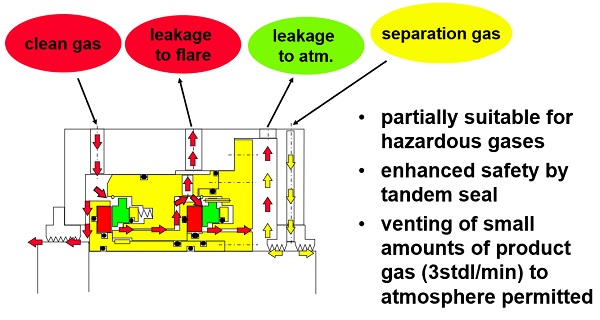 Figure 16 - Tandem seal arrangement Figure 16 - Tandem seal arrangement
Tandem seal with internal labyrinth
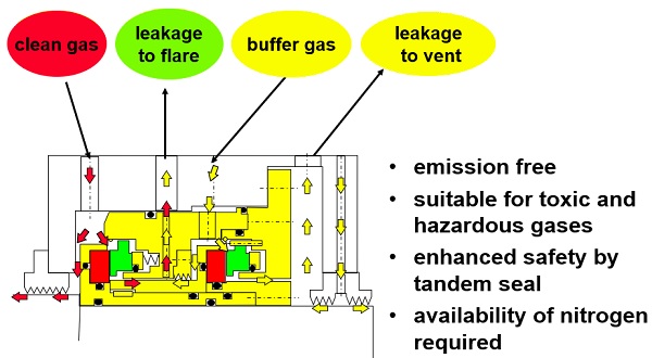 Figure 17 - Tandem seal with internal labyrinth Figure 17 - Tandem seal with internal labyrinth
Double seal arrangement
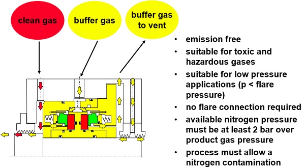 Figure 18 - Double seal arrangement Figure 18 - Double seal arrangement
Seals with O-rings can have the following problems
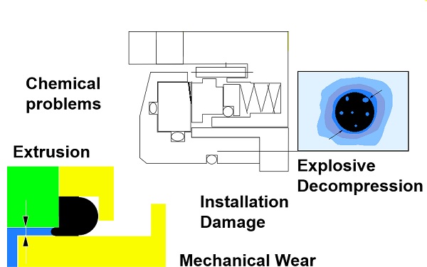 Figure 19 - Seals with O-rings Figure 19 - Seals with O-rings
For some applications the better solution is the Burgmann Polymer Dry Gas Seal (PDGS)
- no chemical problems
- no extrusion
- no explosive decompression
- no mechanical wear
result in: NO HANG UP
Seal configuration Why no hang up
Burgmann Polymer Dry Gas Seals have no hang up because extrusion of secondary sealing elements is not possible due to optimised gaps. Small gaps are possible by using materials with about the same thermal expansion coefficients - Silicon carbide for seal faces and rotating seats and Tungsten carbide for sleeves and back up rings
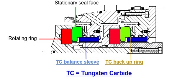 Figure 20 - Seal configuration Figure 20 - Seal configuration
DRY GAS SEAL Operating limits:
- Pmax = 250 bar
- Vgmax = 200 m/s
- Vgmin = dependent on seal design has to be checked!
- Tmax = +230 °C
- Tmin = -170 °C
Current Methods of Sealing Compressors
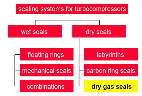 Figure 21 - Sealing Compressors Figure 21 - Sealing Compressors
Current Methods of Sealing Compressors - Labyrinths
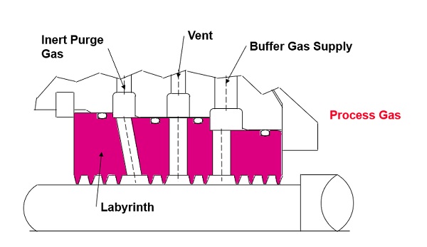 Figure 22- Sealing Compressors - Labyrinths Figure 22- Sealing Compressors - Labyrinths
- Limited application
- Low pressures
- Services such as air, oxygen, chlorine
- High leakage (excessive buffer use)
- Low initial seal cost
- Wear during operation / loose efficiency
- Can require elaborate control systems
Current Methods of Sealing Compressors ( Circumferential Carbon Seals)
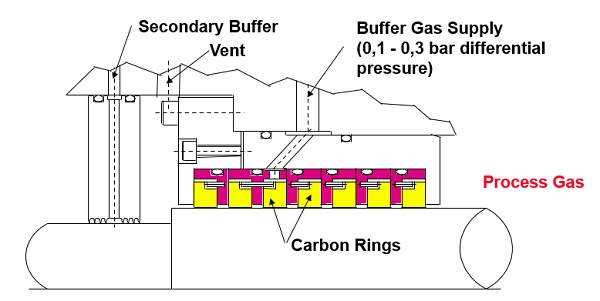 Figure 23 - Current Methods of Sealing Compressors Figure 23 - Current Methods of Sealing Compressors
- Limited application
- Low pressures
- Services such as chlorine
- Moderate leakage (2-3 times < labyrinth)
- Low to moderate initial seal cost
- Wear during operation / lose efficiency
Current Methods of Sealing Compressors (Oil Film Seals)
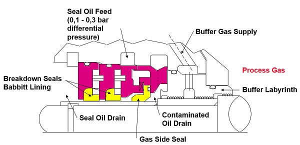 Figure 24 - Current Methods of Sealing Compressors (Oil Film Seals) Figure 24 - Current Methods of Sealing Compressors (Oil Film Seals)
- Pressure Range 0-275 bar
- Oil contamination of the process gas
- Requires minimum pressure / flow to cool
- Wear during operation / lose efficiency
- Elaborate control system
- High power losses
Current Methods of Sealing Compressors (Oil Lubricated Mechanical Seals)
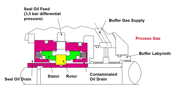 Figure 25 - Current Methods of Sealing Compressors (Oil Lubricated Mechanical Seals) Figure 25 - Current Methods of Sealing Compressors (Oil Lubricated Mechanical Seals)
- Limited in speed and pressure
- Oil contamination of the process gas
- Requires minimum pressure / flow to cool
- Wear during operation / limited life
- Elaborate control system
- High power losses
Why Dry Gas Seals ?
- No oil usage
- High reliabilty
- High Safety
- Maintenance Costs
- Operating Costs
- Process Gas Losses
- Environmental Concerns
- Operating Simplicity
Dry Gas Seal Materials
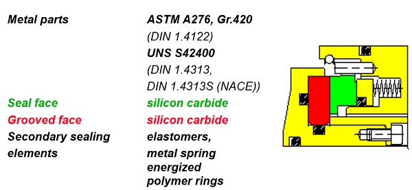 Figure 26 - Dry Gas Seal Materials Figure 26 - Dry Gas Seal Materials
Magnitudes of different face materials
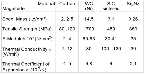 Figure 27 - Different face materials Figure 27 - Different face materials
Essentials of Groove Design
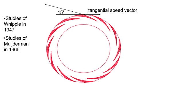 Figure 28 - Essentials of Groove Design Figure 28 - Essentials of Groove Design
Groove entry angle alpha
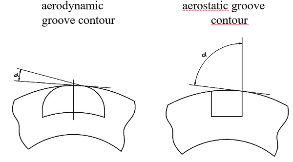 Figure 29 - Groove entry angle alpha Figure 29 - Groove entry angle alpha
uni - directional, V - Groove
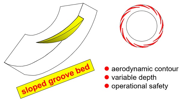 Figure 30 - uni - directional, V - Groove Figure 30 - uni - directional, V - Groove
Dry Gas Seal Principle V-groove
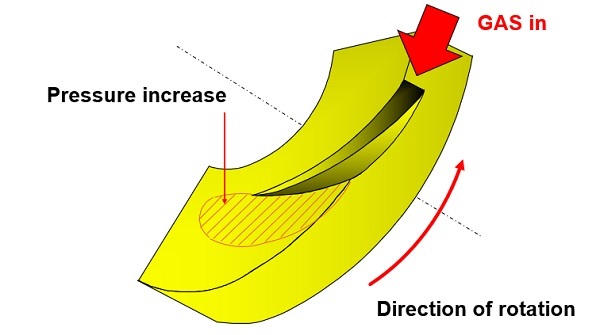 Figure 31 - Dry Gas Seal Principle V-groove Figure 31 - Dry Gas Seal Principle V-groove
bi - directional, U - Groove
 Fiigure 32 - bi - directional, U - Groove Fiigure 32 - bi - directional, U - Groove
Dry Gas Seal Principle U-groove
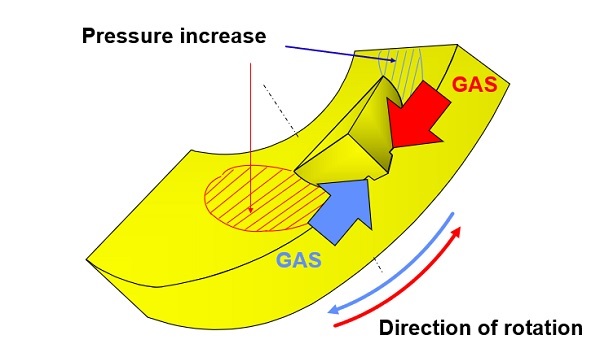 Figure 33 - Dry Gas Seal Principle U-groove Figure 33 - Dry Gas Seal Principle U-groove
Advantages of the Burgmann groove design
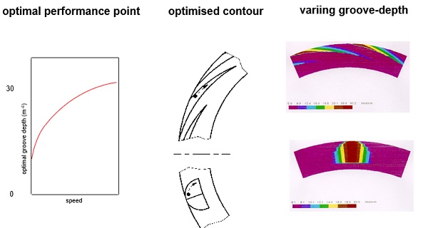 Figure 34 - Advantages of the Burgmann groove design Figure 34 - Advantages of the Burgmann groove design
Forces
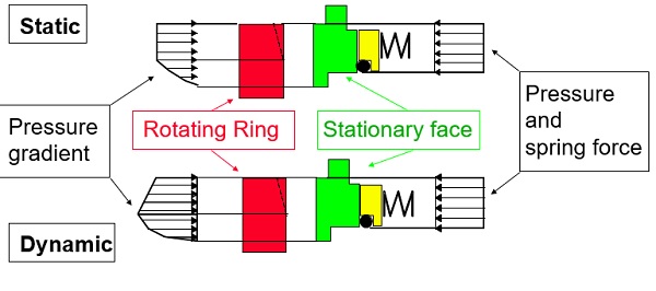 Figure 35 - Forces Figure 35 - Forces
Reaction to transients
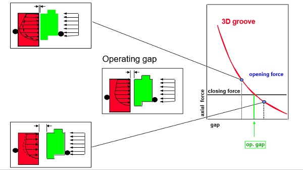 Figure 36 - Reaction to transients Figure 36 - Reaction to transients
Gasfilm - stiffness
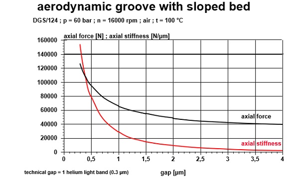 Figure 37 - Gasfilm - stiffness Figure 37 - Gasfilm - stiffness
Single seal arrangement
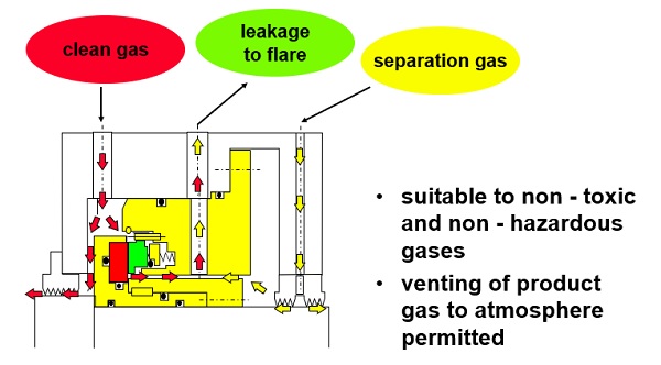 Figure 38 - Single seal arrangement Figure 38 - Single seal arrangement
Tandem seal arrangement
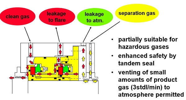 Figure 39 - Tandem seal arrangement Figure 39 - Tandem seal arrangement
Tandem seal with internal labyrinth
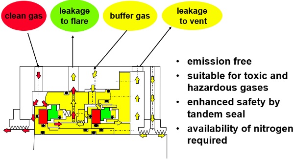 Figure 40 - Tandem seal with internal labyrinth Figure 40 - Tandem seal with internal labyrinth
Double seal arrangement
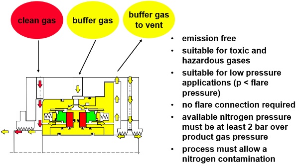 Figure 41 - Double seal arrangement Figure 41 - Double seal arrangement
Operating limits
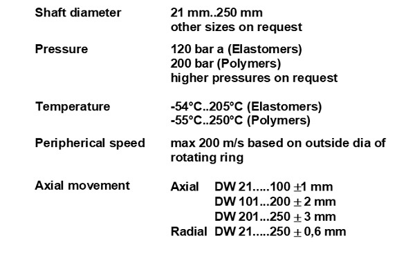 Figure 42 - Operating limits Figure 42 - Operating limits
Leakage
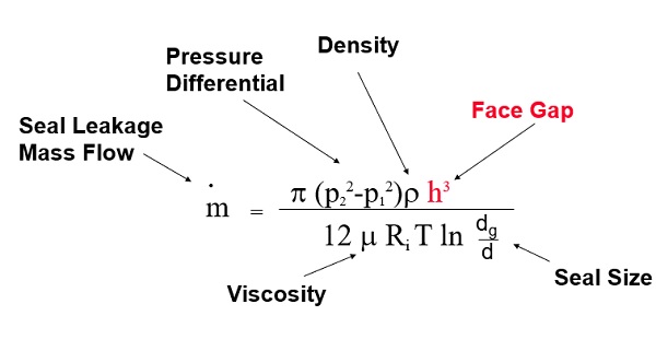 Figure 43 - Leakage Figure 43 - Leakage
Gas Properties
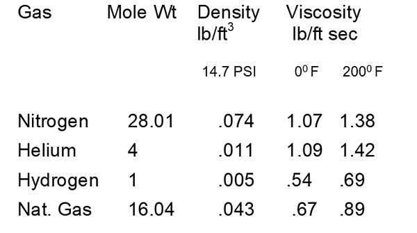 Figure 44 - Gas Properties Figure 44 - Gas Properties
Power Loss
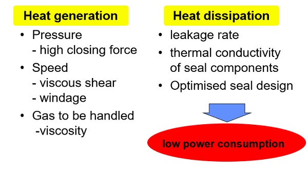 Figure 45 - Power Loss Figure 45 - Power Loss
|


