|
Inconel 718

Developed in the early 1960's, IN718 is still considered the material of choice for the majority of aircraft engine components with service temperatures below 1200°F (650°C). Inconel 718 is a precipitation-hardenable nickel-chromium alloy containing also significant amounts of iron, niobium, and molybdenum along with lesser amounts of aluminum and titanium. It combines corrosion resistance and high strength with outstanding weldability including resistance to post-weld cracking. The alloy has excellent creep-rupture strength at temperatures to 1300°F (700°C).
Standard Specification
Common Names:
- UNS N07718
- Alloy 718
- DIN W. Nr. 2.4668
Plate, Sheet, and Coil:
- ASME SB 670
- ASTM B 670
- B50TF14
- AMS 5596
- UNS N07718
Round Bar:
- AMS 5662
- B50809D
- UNS N07718
- B50TF15
- ASTM B 637
Chemical Composition Inconel 718
Inconel 718
|
%
|
Nickel
|
Ni
|
50 - 55 |
| Chromium |
Cr
|
17 - 21
|
| Iron |
Fe
|
Balance
|
| Molybdenum |
Mo |
2.80 - 3.30
|
| Columbium |
Cb |
4.75 - 5.50 |
| Carbon (Max) |
C
|
0.08 max
|
| Manganese (Max) |
Mn
|
0.35 max
|
| Sulfur (Max) |
S
|
0.015 max
|
| Aluminum |
AI |
0.20 - 0.80
|
| Silicon (Max) |
Si
|
0.35 max |
| Phosphorus |
P |
0.015 max |
| Titanium |
Ti
|
0.65 - 1.15
|
| Cobalt |
Co |
1.0 max |
| Boron |
B |
0.006 max |
| Copper |
Cu |
0.30 max |
| Tantalum |
Ta |
0.05 max |
Table 1 - Chemical Composition
Applications of Inconel 718
- Jet engine
- Gas turbine operations
- Base plates
- Rotor bolts (Power generation)
- Burst discs
- Springs
- Hold-down springs for nuclear components
- Seal rings
- Components for gas turbine
- Instrumentation parts
- Fasteners
Physical Properties
718 Inconel is an alloy often used in engineering and aerospace applications requiring a combination of high strength and corrosion resistance. It has a yield strength greater than 90 ksi, making it a material preferred for components and parts requiring considerable strength. The Young’s modulus for Inconel 718 is around 28msi, resulting in good formability, ductility and weldability. Additionally, it has excellent creep-rupture properties at 1300°F and can tolerate temperature extremes ranging from -422°F to 1500°F depending on heat treatment condition. As such, Inconel 718 is often used in high-temperature engine and airframe components due to the robust physical properties that make it an ideal material for challenging engineering conditions.
| Density |
Melting Range |
Specific Heat |
Thermal Expansion (Mean Coefficient)
|
Magnetic Permeability |
Annealed |
| lb/in.3 |
g/cm3 |
°F |
°C |
70°F, Btu/lb-°F |
21°C, J/kg-°C |
in/in/° |
mm/m/°C
|
Oersteds |
-- |
| 0.296 |
8.19 |
2300-2437 |
1260-1336 |
0.104 |
435 |
7.6 X 10 |
13.0 |
200 |
1.013 |
| Annealed + Aged |
Elasticity Modulus |
|
| -- |
Ksi |
Mpa |
| 1.011 |
29.7 X 10³ |
204.9 X 10³ |
Table 2 - Physical Properties
Mechanical Properties
This combination gives the alloy excellent mechanical properties like high tensile strength, yield strength, creep resistance, fatigue life, oxidation resistance, and corrosion resistance. The alloy also has good thermal stability, which means it can be used in temperatures up to 1300 degrees Fahrenheit without losing its mechanical or chemical properties.
|
Temperature °F
|
Modulus of Elasticity, ksi x 103
|
Poisson’s Ratiob
|
Temperature °F
|
Modulus of Elasticity, ksi x 103
|
Poisson’s Ratiob
|
|
Young’s Modulus
|
Torsional Modulus
|
Young’s Modulus
|
Torsional Modulus
|
|
70
|
29.0
|
11.2
|
0.294
|
1300
|
23.0
|
8.9
|
0.292
|
|
100
|
28.8
|
11.2
|
0.291
|
1400
|
22.3
|
8.5
|
0.306
|
|
200
|
28.4
|
11.0
|
0.288
|
1500
|
21.3
|
8.1
|
0.321
|
|
300
|
28.0
|
10.9
|
0.280
|
1600
|
20.2
|
7.6
|
0.331
|
|
400
|
27.6
|
10.8
|
0.280
|
1700
|
18.8
|
7.1
|
0.334
|
|
500
|
27.1
|
10.6
|
0.275
|
1800
|
17.4
|
6.5
|
0.341
|
|
600
|
26.7
|
10.5
|
0.272
|
1900
|
15.9
|
5.8
|
0.366
|
|
700
|
26.2
|
10.3
|
0.273
|
2000
|
14.3
|
5.1
|
0.402
|
|
800
|
25.8
|
10.1
|
0.271
|
a Hot-rolled flat heat-treated 1800°F/1 hr, A.C. + 1325°F/8 hr, F.C. 20°F/hr to 1150°F, held for total aging time of 18 hr. Dynamic testing involved frequencies of from 813 to 571 cps in bending and from 3110 to 2097 cps in torsion.
b Computed from (E-2G)/2G, where E is Young’s Modulus and G is torsional modulus.
|
|
900
|
25.3
|
9.9
|
0.272
|
|
1000
|
24.8
|
9.7
|
0.271
|
|
1100
|
24.2
|
9.5
|
0.276
|
|
1200
|
23.7
|
9.2
|
0.283
|
Table 3 - Modulus of Elasticity
| Temperature °F |
Thermal Conductivity, a
BTU•in/ft2•h•°F
|
Electrical Resistivity, a
ohm circ mil/ft
|
Mean Linear Expansion b,c,
in/in/°F x 10-6
|
|
Ann. 1800°F/1 hr
|
Ann. + Aged
|
Ann. 1800°F/1 hr
|
Ann + Aged
|
|
-320
|
-
|
-
|
-
|
-
|
5.9d
|
|
70
|
77
|
79
|
753
|
725
|
-
|
|
200
|
86
|
87
|
762
|
733
|
7.31
|
|
400
|
98
|
100
|
772
|
755
|
7.53
|
|
600
|
111
|
112
|
775
|
768
|
7.74
|
|
800
|
123
|
124
|
784
|
775
|
7.97
|
|
1000
|
135
|
136
|
798
|
788
|
8.09
|
|
1200
|
147
|
148
|
805
|
794
|
8.39
|
|
1400
|
160
|
161
|
802
|
797
|
8.91
|
|
1600
|
173
|
173
|
799
|
796
|
-
|
|
1800
|
185
|
186
|
801
|
800
|
-
|
|
2000
|
196
|
199
|
811
|
796
|
-
|
- a Annealing was 1800°F/1 hr; aging was 1325°F/8 hr, F.C. 20°/hr to 1150°F, held at 1150°F for total aging time of 18 hr. Conductivity is calculated from resistivity values.
- b From 70°F to the temperature shown.
- c Annealed 1750°F/1 hr and aged 1325°F/8 hr, F.C. to 1150°F/8 hr, A.C.
- d Samples tested were in both the annealed (1750°F/1 hr, A.C.) and annealed and aged (1750°F/1 hr + 1325°F/8 hr, F.C. to 1150°F, held at 1150°F for 10 hr, A.C.) conditions
|
Table 4 - Thermal Properties
Work condition and Heat Resistance of Inconel 718
It also has excellent heat resistance, making it suitable for applications that involve very high temperatures, like jet engine components or combustion chambers in cars or motorcycles.
The alloy is used in jet engines and high-speed airframe parts such as wheels, buckets and spacers, and high-temperature bolts and fasteners. Inconel 718 is also used in the oil and gas drilling and production industries due to its high strength and resistance to chlorides, stress corrosion and sulfide stress cracking. Within these industries, the alloy has been used for valves, pump shafts and wellhead components. Inconel 718 Slit Coil, Inconel® 718 Sheets, Inconel Alloy 718 CR Plates, WNR. 2.4668 Sheets, Inconel 718 Sheets, UNS N07718 Plates, Alloy 718 Circle, Inconel Alloy 718 Plates Distributors. The addition of molybdenum and niobium makes the alloy stiffen thus providing high strength with no heat treatment. They can be readily welded and fabricated in precipitated or annealed hardened conditions. These superalloys are made available in various dimensions, specifications, and sizes that ultimately make is suitable for marine engineering, chemical processing, and other applications too.
Hot and Cold Forming
Because of its strength, Alloy 718 is more resistant than most materials to deformation during hot forming. Its relative resistance is shown by pressures developed in the roll gap at 20% reduction (Table 5). It is readily hot-worked if sufficiently powerful equipment is used. Hot forming is performed in the 1650°-2050°F temperature range. In the last operation, the metal should be worked uniformly with a gradually decreasing temperature, finishing with some light reduction in the 1650°-1750°F range. This procedure is necessary to ensure notch ductility in stress-rupture applications when the material has been annealed and aged. In heating for hot working, the material should be brought up to temperature, allowed to soak a short time to ensure uniformity, and withdrawn.
To avoid duplex grain structure Alloy 718 should be given uniform reductions. Final reductions of 20% minimum should be used for open-die work and 10% minimum for closed-die work. Parts should generally be air-cooled from the hot working temperature rather than water-quenched. Care should be taken to avoid overheating the metal by heat build-up due to working. Also, the piece should be reheated when any portion has cooled below 1650°F. Preheating tools and dies to 500°F is recommended. Any ruptures appearing on the surface of the workpiece must be removed at once.
Data shown in Table 48 show the importance of a 1650°F-1750°F finish-forging temperature for the achievement of notch ductility in large forgings in stress-rupture applications. In these tests, a 0.75-in. square forged bar was cut into 12-in. lengths, heated to the rolling temperatures shown in Table 6 and 7, and given a 25% reduction in one pass. Following annealing and aging, specimens were ruptured tested at 1200°F and 100 ksi. Success in achieving notch rupture ductility with forgings of alloy 718 through this type of procedure has also been reported by others.
| Material |
Pressure, ksi
|
|
Hot-Forming Temperature, °F
|
|
1800
|
1900
|
2000
|
2100
|
|
Mild Steel (1020)
|
22.4
|
18.3
|
14.3
|
10.3
|
|
Type 302 Stainless Steel
|
27.8
|
24.3
|
21.4
|
18.0
|
|
INCONEL alloy 600
|
40.8
|
34.6
|
28.3
|
22.3
|
|
INCONEL alloy X-750
|
48.6
|
43.3
|
38.4
|
33.3
|
|
INCONEL alloy 718
|
63.3
|
55.8
|
48.3
|
41.0
|
Table 5 - Pressure, ksi, Developed in Roll Gap at 20% Reduction
| Hot-Forming Temperature, °F |
Heat Treatment b |
ASTM Grain Size |
Smooth Bar
|
Notch Bar Life c,
hr
|
| Life hr |
Elongation,
%
|
Reduction of area, % |
Hardness Rc |
|
2050
|
A
|
20% 0.5, 30% 4.5, 40% 6.5, 10% 9
|
193.5 |
3
|
6.5
|
45
|
16.2
|
|
B
|
100% 1.5
|
209.5 |
4
|
8.5
|
46
|
16.5
|
|
1950
|
A
|
70% 8, 30% 3
|
274.5 |
7
|
9.0
|
45
|
55.1
|
|
B
|
60% 3, 30% 8, 10% 7
|
291.4 |
8
|
10.0
|
45
|
56.7
|
|
1850
|
A
|
95% 4.5, 5% 9
|
193.3 |
11
|
16.0
|
46
|
123.9
|
|
B
|
35% 4.5, 60% 9, 5% 7
|
231.6 |
10
|
13.0
|
46
|
99.2
|
|
1750
|
A
|
20% 6, 20% 7, 60% 10
|
121.3 |
13
|
22.0
|
46
|
131.4
|
|
B
|
40% 7, 55% 9, 5% 5
|
248.3 |
14
|
16.0
|
46
|
179.6
|
|
1650
|
A
|
100% 9.5
|
48.0 |
33
|
53.5
|
46
|
426.2d
|
|
B
|
100% 9.5
|
124.3 |
28
|
43.5
|
46
|
426.1d
|
- a Hot-finished, 25% reduction, one pass.
- b A--1750°F/1 hr, A.C., + 1325°F/8 hr, F.C. 100°F/hr to 1150°F, hold at 1150°F/8 hr, A.C.
- B--1800°F/1 hr, A.C., + 1325°F/8 hr, F.C. 100°F/hr to 1150°F, hold at 1150°F/8 hr, A.C.
- c Kt, 3.5 to 4.0; root diameter, 0.252-in.
- d Test discontinued
|
Table 6 - Effect of Hot-Forging Temperature on Rupture Properties (1200°F, 100 ksi)
|
Cold Reduction,
%
|
Tests at Room Temperature
|
Tests at -320°F
|
|
Tensile Strength,
ksi
|
Yield Strength (0.2% Offset),
ksi
|
Elongation,
%
|
Hardness, Rc
|
Tensile
Strength, ksi
|
Yield Strength
(0.2% Offset), ksi
|
Elongation,
%
|
|
0
|
117.0
|
44.0
|
60.0
|
87 Rb
|
-
|
-
|
-
|
| 5.9 |
115.0
|
68.2
|
45.0
|
19
|
161.0
|
103.0
|
38.0
|
| 18.5 |
145.0
|
116.5
|
25.0
|
33
|
189.0
|
153.0
|
24.0
|
| 27.9 |
159.5
|
134.0
|
10.5
|
36
|
204.0
|
169.0
|
15.0
|
| 48.3 |
191.0
|
165.0
|
7.0
|
40
|
231.0
|
204.0
|
15.0
|
| Aged 1325°F/8 hr, F.C. 100°F/1 hr to 1150°F (Held for Total Aging Time of 18 hr, A.C.) after Cold Rolling |
| 0 |
187.0 |
172.5 |
19.5 |
44 |
248.0 |
188.5 |
26.0 |
| 5,9 |
203.0 |
175.5 |
22.0 |
45 |
255.0 |
211.0 |
13.0 |
| 18.5 |
217.0 |
201.0 |
16.0 |
47 |
270.0 |
235.0 |
12.5 |
| 48.3 |
244.0 |
201.0 |
4.0 |
49 |
289.0 |
269.0 |
2.5 |
Table 7 - Effect of Cold Reduction on Properties of Sheet
INCONEL alloy 718 can be cold-formed by standard procedures used for steel and stainless steel. Figure 1 below shows its rate of work hardening in comparison with other materials. The effect of cold reduction on the tensile properties of the sheet in the cold-rolled and cold-rolled and aged conditions is shown in Table 7.
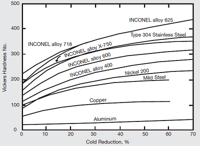 Figure 1 - Effect of cold work on hardness. Figure 1 - Effect of cold work on hardness.
Corrosion Resistance of Inconel 718
The high chromium content of Inconel 718 makes it highly resistant to corrosion from strong acids like hydrochloric acid or sulfuric acid at room temperature or elevated temperatures up to 1000°C (1800°F).
Alloy 718 has excellent corrosion resistance to many media. This resistance, which is similar to that of other nickel-chromium alloys, is a function of its composition. Nickel contributes to corrosion resistance in many inorganic and organic, other than strongly oxidizing, compounds throughout wide ranges of acidity and alkalinity. It also is useful in combating chloride-ion stress-corrosion cracking. Chromium imparts an ability to withstand attack by oxidizing media and sulfur compounds. Molybdenum is known to contribute to resistance to pitting in many media.
Stress-Corrosion Cracking
Alloy 718 is generally considered a highly corrosion-resistant material but can still be susceptible to stress corrosion cracking (SCC). The combination of factors leading to SCC susceptibility in the alloy is not always clear enough. For more details click here
Fabrication
Inconel 718 alloy can be readily machined however the strength and work toughening features should be considered while choosing and using the precise apparatus alloys and design, processing speed and quenchers. When machining in the age-toughened form, the strip offers the enhanced finish, and chip performance on the chip breaker tools are enhanced. If annealed alloy is used, it provides more convenient machining and extended tool life.
Machinability
Nickel & cobalt base corrosion, temperature and wear-resistant alloys, such as Inconel 718, are classified as moderate to difficult when machining, however, it should be emphasized that these alloys can be machined using conventional production methods at satisfactory rates. During machining these alloys work to harden rapidly, generate high heat during cutting, weld to the cutting tool surface and offer high resistance to metal removal because of their high shear strengths. The following are key points which should be considered during machining operations:
- CAPACITY - The machine should be rigid and overpowered as much as possible.
- RIGIDITY - The workpiece and tool should be held rigid. Minimize tool overhang.
- TOOL SHARPNESS - Make sure tools are sharp at all times. Change to sharpened tools at regular intervals rather than out of necessity. A 0.015-inch wear land is considered a dull tool.
- TOOLS - Use positive rake angle tools for most machining operations. Negative rake angle tools can be considered for intermittent cuts and heavy stock removal. Carbide-tipped tools are suggested for most applications. High-speed tools can be used, with lower production rates, and are often recommended for intermittent cuts.
- POSITIVE CUTS - Use heavy, constant, feeds to maintain positive cutting action. If feed slows and the tool dwells in the cut, work hardening occurs, tool life deteriorates and close tolerances are impossible.
- LUBRICATION - Lubricants are desirable, and soluble oils are recommended especially when using carbide tooling. Detailed machining parameters are presented in Tables 8 and 9. General plasma cutting recommendations are presented in Table 10.
| RECOMMENDED TOOL TYPES AND MACHINING CONDITIONS |
|---|
| Operations |
Carbide Tools |
| Roughing, with severe interruption |
Turning or Facing C-2 and C-3 grade: Negative rake square insert, 45 degrees SCEA1, 1/32 in. nose radius. Tool holder: 5 degree neg. back rake, 5 degree neg. side rake. Speed: 30-50 sfm, 0.004-0.008 in. feed, 0.150 in depth of cut. Dry2, oil3, or water-base coolant4. |
| Normal roughing |
Turning or Facing C-2 or C-3 grade: Negative rate square insert, 45-degree SCEA, 1/32 in nose radius. Tool holder: 5 degree neg. back rake, 5 degree neg. side rake. Speed: 90 sfm depending on rigidity of set up, 0.010 in. feed, 0.150 in. depth of cut. Dry, oil, or water-base coolant. |
| Finishing |
Turning or Facing C-2 or C-3 grade: Positive rake square insert, if possible, 45 degrees SCEA, 1/32 in. nose radius. Tool holder: 5-degree pos. back rake, 5-degree pos. side rake. Speed: 95-110 sfm, 0.005-0.007 in. feed, 0.040 in. depth of cut. Dry or water-base coolant. |
| Rough Boring |
C-2 or C-3 grade: If inserting type boring bar, use standard positive rake tools with the largest possible SCEA and 1/16 in. nose radius. If brazed tool bar, grind 0 degrees back rake, 10-degree pos. side rake, 1/32 in. nose radius and largest possible SCEA. Speed: 70 sfm depending on the rigidity of setup, 0.005-0.008 in. feed, 1/8 in. depth of cut. Dry, oil or water-base coolant. |
| Finish Boring |
C-2 or C-3 grade: Use standard positive rake tools on insert-type bars. Grind brazed tools as for finish turning and facing except back rake may be best at 0 degrees. Speed: 95-110 sfm, 0.002-0.004 in feed. Water-base coolant. |
| Notes: |
- 1 - SCEA - Side cutting edge angle or lead angle of the tool.
- 2 - At any point where dry cutting is recommended, an air jet directed on the tool may provide substantial tool life increases. A water-based coolant mist may also be effective.
- 3 - Oil coolant should be premium quality, sulfochlorinated oil with extreme pressure additives. A viscosity at 100 degrees F from 50 to 125 SSU.
- 4 - Water-base coolant should be premium quality, sulfochlorinated water soluble oil or chemical emulsion with extreme pressure additives. Dilute with water to make 15:1 mix. Water-base coolant may cause chipping and rapid failure of carbide tools in interrupted cuts.
|
Table 8 - Tool Type and Matching Conditions
| RECOMMENDED TOOL TYPES AND MACHINING CONDITIONS |
|---|
| Operations |
Carbide Tools |
| Facing Milling |
Carbide is not generally successful, C- grade may work. Use positive axial and radial rake, 45-degree corner angle, and 10-degree relief angle. Speed: 50-60 sfm. Feed: 0.005-0.008 in. Oil or water-base coolants will reduce thermal shock damage of carbide cutter teeth. |
| End Milling |
Not recommended, but C-2 grades may be successful on good setups. Use positive rake. Speed: 50-60 sfm. Feed: Same as high-speed steel. Oil or water-base coolants will reduce thermal shock damage. |
| Drilling |
C-2 grade is not recommended, but tipped drills may be successful on rigid setup if no great depth. The web must thinned to reduce thrust. Use 135 degrees including angle on point. Gun drills can be used. Speed: 50 sfm. Oil or water-base coolant. Coolant-feed carbide-tipped drills may be economical in some setups. |
| Reaming |
C-2 or C-3 grade: Tipped reamers are recommended, solid carbide reamers require a very good setup. Tool geometry same as high-speed steel. Speed: 50 sfm. Feed: Same as high-speed steel. |
| Tapping |
Not recommended, machine threads, or roll-form them. |
| Electrical Discharge Machining |
The alloys can be easily cut using any conventional electrical discharge machining system (EDM) or wire (EDM). |
| Notes: |
- 5 - M-40 series High Speed Steels include M-41 , M-42, M-43, M-44, M-45 and M-46 at the time of writing. Others may be added and should be equally suitable.
- 6 - Oil coolant should be a premium quality, sulfochlorinated oil with extreme pressure additives. A viscosity at 100 degrees F from 50 to 125 SSU.
- 7 - Water-base coolant should be premium quality, sulfochlorinated water soluble oil or chemical emulsion with extreme pressure additives. Dilute with water to make 15:1 mix.
|
Table 9 - Tool Type and Matching Conditions
| Plasma Arc Cutting |
|---|
| Inconel 718 can be cut using any conventional plasma arc cutting system. The best arc quality is achieved using a mixture of argon and hydrogen gases. Nitrogen gas can be substituted for hydrogen gases, but the cut quality will deteriorate slightly. Shop air or any oxygen-bearing gases should be avoided when plasma cutting these alloys. |
Table 10 - General plasma cutting
Welding of Inconel 718
Welding can be done using several different welding processes like Gas Tungsten Arc Welding(GTAW), Plasma arc welding(PAW), Gas Metal Arc Welding(GMAW) etc., depending on the size/shape/location/thickness of the weld joint required for joining two pieces together using this material, e.g., GTAW would be preferred when welding thin sections. At the same time, GMAW would be suitable when welding thicker sections with larger weld beads, etc.
INCONEL alloy 718 is readily welded by the gas tungsten arc (TIG) process using INCONEL Filler Metal 718. The composition of this filler metal is shown in Table 11. The mechanical properties of its all-weld metal specimens are shown in Table 1 above. These test data show the effect of postwelding treatment on tensile properties. The highest room temperature ductility is obtained by annealing at 1950°F prior to ageing.
|
Filler Metal
Diameter, in. a
|
Heat Treatment b |
Tensile Strength, ksi |
Yield Strength (0.2% Offset), ksi |
Elongation,
%
|
Reduction of Area, % |
|
0.045
|
As-Welded c
|
125.50
|
84.30
|
28.0
|
30.0
|
|
|
1750°F, Age
|
180.25
|
148.50
|
7.8
|
12.3
|
|
|
1950°F, Age
|
197.25
|
162.75
|
18.8
|
26.5
|
|
|
1325°F, Age
|
186.00
|
153.50
|
11.0
|
13.5
|
|
0.045
|
As-Welded
|
120.75
|
82.30
|
28.0
|
30.5
|
|
|
1750°F, Age
|
169.50
|
144.00
|
7.8
|
12.0
|
|
|
1950°F, Age
|
193.50
|
164.85
|
13.3
|
17.0
|
|
|
1325°F, Age
|
180.50
|
147.75
|
7.8
|
10.3
|
|
0.09375
|
As-Welded
|
123.75
|
84.00
|
28.0
|
31.3
|
|
|
1750°F, Age
|
174.50
|
145.25
|
7.7
|
12.5
|
|
|
1950°F, Age c
|
197.00
|
168.50
|
10.0
|
18.0
|
|
|
1325°F, Agec
|
166.50
|
150.50
|
4.0
|
4.0
|
|
0.062
|
As-Welded c
|
125.20
|
83.50
|
28.0
|
37.5
|
|
|
1750°F, Age
|
174.50
|
152.00
|
4.9
|
7.0
|
|
|
1950°F, Age
|
198.00
|
179.25
|
13.8
|
21.5
|
|
|
1325°F, Age c
|
175.50
|
151.00
|
4.0
|
7.5
|
|
0.062
|
As-Welded
|
123.25
|
75.05
|
34.3
|
35.3
|
|
|
1750°F, Age
|
180.00
|
144.00
|
12.6
|
18.0
|
|
|
1950°F, Age c
|
196.50
|
161.00
|
16.0
|
31.0
|
|
|
1325°F, Age
|
176.75
|
140.00
|
15.5
|
22.5
|
- a Each separate size shown represents test run on separate heat.
- b Heat treatments: 1750°F, Age is 1750°F anneal plus age at 1325°F/8 hr , F.C. 100°F/hr to 1150°F, hold at 1150°F for a total of 18 hours. 1950°F, Age is 1950°F anneal plus age at 1400°F/10 hr, F.C. 100°F/hr to 1200°F, hold at 1200°F for a total aging time of 20 hours. 1325°F, Age is at 1325°F/8 hr, F.C. 100°F/hr to 1150°, hold at 1150°F for total aging time of 18 hr.
- c One test only
|
Table 11 - Effect of Post Welding Heat Treatment on Tensile Properties of INCONEL Filler Metal 718 All-Weld Metal (Manual Gas Tungsten-Arc Process between 0.5-in. Plates) (Average of 2 Tests)
Slow response of alloy 718 to age hardening enables parts to be welded and directly age-hardened without intermediate stress relief. Joint efficiencies very close to 100% were realized in the tests shown in Table 12; these specimens were from plate that had been annealed, then welded and aged. Better properties, however, are obtained by re-annealing after welding prior to ageing.
| Tensile Strength, ksi |
Yield Strength (0.2% Offset), ksi
|
Elongation in 1 ln.,
%
|
Reduction of Area,
%
|
|
|
Transverse Tests Across Joints |
|
| 183.0 |
159.5
|
8.0 |
19.0 |
| 183.5 |
158.5
|
7.0 |
16.0 |
| 186.5 |
162.0
|
6.0 |
12.8 |
| 185.5 |
163.0
|
6.0 |
21.0 |
| 184.0 |
163.0
|
6.0 |
16.5 |
| 192.5 |
166.0
|
9.0 |
17.5 |
| 191.5 |
164.0
|
6.0 |
12.5 |
| 182.0 |
156.5
|
4.0 |
6.8 |
| 188.5 |
168.0
|
4.0 |
11.5 |
| 188.0 |
170.0
|
5.0 |
10.0 |
| Average 186.5 |
163.0
|
6.0 |
14.4 |
|
|
All-Weld Metal Tests |
|
| 180.5 |
157.5
|
10.0 |
16.0 |
| 182.5 |
162.0
|
8.0 |
14.0 |
| 178.0 |
154.0
|
11.0 |
12.5 |
| 177.5 |
150.0
|
14.0 |
18.5 |
| 180.0 |
153.5
|
10.0 |
22.0 |
| 180.0 |
158.5
|
7.0 |
11.5 |
| 183.5 |
160.5
|
6.0 |
8.5 |
| Average 180.0 |
156.5
|
9.0 |
15.0 |
Table 12 - Room Temperature Tensile Properties of Welds (Aged 1325°F/8 hr, F.C. to 1150°F, Held at 1150°F for Total Aging Time of 18 Hours)
Silver brazing compounds are known to cause stress cracking in nickel-based alloys. If alloy 718 is cold-worked and/or precipitation-hardened, silver brazing compounds should not be used. Also, brazing alloys containing cadmium are best avoided; while cadmium has not been shown to cause cracking by itself, it can aggravate cracking from other sources.
Weld Tensile Properties
Room-temperature properties of welds receiving the low-temperature anneal and/or age can be compared with the results of the high-temperature anneal and/or age in Tables 12 and 13
Additional properties of welds annealed at 1950°F/15 min. and aged at 1400°F/10 hr, F.C. to 1200°F, hold at 1200°F for a total ageing time of 20 hours are shown in Table 14. Welding was done by the manual gas tungsten-arc process, using Filler Metal 718. These welds were found satisfactory in bend tests and radiographic examination. Slightly better results were obtained when helium was used as the torch gas. The notch strength of the butt-welded sheet in both the heat-affected zone and weld is shown in Table 15. These welds were heat-treated by the low-temperature schedule.
Another laboratory using the high-temperature heat treatment has found that the notch toughness of the parent metal and that of the weld metal are quite consistent and exceed a notch-to-smooth bar tensile ratio of 1.30 throughout the test temperature range of -423°F to 1200°F. Test data are shown in Table 16. The weld joint efficiency is approximately 93% at -423°F and 95% at room temperature and 1200°F. For more details regarding the welding system click here.
| Sample |
Postweld Heat Treatmentb |
Tensile Strength, ksi |
Yield
Strength (0.2 %
Offset), ksi
|
Elongation in 0.5 ln.,
%
|
Reduction of Area,
%
|
|
All-Weld Metal
|
Direct Age
|
174.50
|
139.25
|
18.3
|
21.5
|
|
|
1950°F/1 hr, Age
|
185.75
|
155.50
|
22.0c
|
31.8
|
|
Transverse d
|
Direct Age
|
183.50
|
149.50
|
12.0
|
24.8
|
|
|
1950°F/1 hr, Age
|
192.25
|
160.75
|
17.3
|
23.5
|
- a Average of 2 tests.
- b Age--1400°F/10 hr, F.C. to 1200°F, hold at 1200°F for total aging time of 20 hours.
- c One test.
- d All fractures were in the weld.
|
Table 13 - Room-Temperature Tensile Properties of Welds in 0.5-in. Plate (Gas Tungsten-Arc Process Using INCONEL Filler Metal 718)
|
| Weld |
Tensile Strength, ksi |
Elongation ln 1 in., % |
| Argon Torch Gas; Helium Root Gas |
| 1 |
188.00
|
11.7 |
| 2 |
184.20
|
10.0 |
| 3 |
184.50
|
10.0 |
| 4 |
190.20
|
14.3 |
| 5 |
192.70
|
17.3 |
| |
Average 187.92 |
12.7 |
| Helium Torch Gas; Argon Root Gas |
| 6 |
189.20 |
11.7 |
| 7 |
191.00 |
15.3 |
| 8 |
187.80 |
12.7 |
| 9 |
191.70 |
18.3 |
| 10 |
194.00 |
18.7 |
|
Average 190.74 |
15.3 |
| a Welded manually with INCONEL FIller Metal 718. One bead. Average of 3 tests. All sheet from the same heat. Heat treatment after welding: 1950°F/15 min., plus 1400°F/10 hr, F.C. to 1200°F, hold at 1200°F for total aging time of 20 h |
Table 14 - Room-Temperature Tensile Properties of Annealed and Aged Welds in 0.063-in. Sheet a
|
| Treatment of Welda |
Notch Strengthb, ksi |
| Heat-Affected Zone |
Weld |
| Aged |
154.0
|
129.0
|
| |
183.8 |
133.5 |
| Annealed |
175.0
|
132.3
|
| 1800°F/1 hr and Aged |
163.3
|
136.0
|
- a Aging--1325°F/8 hr, F.C. to 1150°F, hold for the total ageing time of 18 hr, A.C. All welds milled flush to the parent metal. Welds made by automatic gas tungsten-arc process with INCONEL Filler Metal 718.
- b Average of 2 values. Notches were milled in the center of the weld and in the parent metal about 0.025-in. from the fusion zone Kt, approximately 24.
|
Table 15 - Notch-Strength of Butt-Welded, 0.051-in. Cold-Rolled, Annealed Sheet
|
| Specimen |
Tensile Strength, ksi
|
Yield Strength
(0.2% Offset), ksi
|
Elongation,
%
|
Reduction
of Area,
%
|
Notch Tensile Strengthb, ksi
|
Notch/Unnotch
Tensile strength ratio
|
|
Room Temp.
|
|
|
|
|
|
|
| Parent Metal |
197.5
|
163.8
|
25.5
|
38.5
|
272.8
|
1.38
|
| Weld |
189.7
|
165.6
|
19.3
|
38.1
|
263.1
|
1.39
|
| -423°F |
|
|
|
|
|
|
| Parent Metal |
245.9
|
203.6
|
22.5
|
33.1
|
323.8
|
1.32
|
| Weld |
237.9
|
201.0
|
19.7
|
30.7
|
308.7
|
1.30
|
| 1200°F |
|
|
|
|
|
|
| Parent Metal |
143.8
|
125.7
|
21.1
|
40.7
|
207.4
|
1.44
|
| Weld |
147.3
|
127.3
|
11.9
|
30.2
|
204.2
|
1.39
|
- a Data are averages of 2-5 tests.
- b Notch concentration factor, Kt, 6.3
|
Table 16 - Tensile Properties of Ring-Forging Specimens Gas-Tungsten-Arc Welded with INCONEL filler Metal 718 (Weldments Annealed 1950°F/1 hr and Aged 1400°/10 hr, F.C. to 1200°F, Hold at 1200°F for Total Aging Time of 20 hours) a
|
|
Weld Fatigue Properties
Weldments were found to have a room-temperature fatigue strength (108 cycles) of approximately 62.5 ksi (tested in R.R. Moore rotating-beam apparatus). They were made from hot-rolled, annealed (per AMS 5596) 0.500-in. plate, joined with 0.125-in.-diameter INCONEL Filler Metal 718 by the gas tungsten arc process. Samples were aged 1325°F/8 hr, F.C. to 1150°F, hold at 1150°F for the total ageing time of 18 hours and tested as polished specimens. In incomparable tests, alloy 718 bar had a fatigue strength (108 cycles) of 89.0 ksi.
Weld Rupture Properties
Rupture strength at 1200° and 1300°F of heat-treated weldments in sheet is compared with parent metal in Table 17. In other tests, welds whose process steps were age, weld, and age had lives of 0.3 hr (1200°F, 100.0 ksi) and 4.9 hr (1300°F, 72.5 ksi); fractures were in the heat-affected zone. Notch-bar life at 1300°F and 75.0 ksi is shown in Table 18.
| Treatment of Weld |
Test Temperature, °F |
Stress, ksi
|
Life, hr
|
Elongation,
%
|
Location of Fracture |
|
Parent Metal Annealed
and Aged
|
1200
|
100.0
|
47.3
|
85.0
|
-
|
|
1300
|
72.5
|
26.1
|
11.0
|
-
|
|
Annealed and Aged
|
1200
|
100.0
|
10.8
|
1.0
|
Weld
|
|
1300
|
72.5
|
9.4
|
1.0
|
Weld
|
|
Aged
|
1200
|
100.0
|
16.4
|
1.0
|
Weld
|
|
1300
|
72.5
|
15.8
|
2.0
|
Weld
|
- a 0.060-in. sheet, welded with INCONEL FIller Metal 718. Parent metal and weld heat-treated in accordance with AMS 5596. Welds ground flush.
|
Table 17 - Rupture Strength of Butt Joints in Annealed Sheet a
| Specimen |
Heat Treatment b |
Life, hr
|
Elongation,
%
|
Reduction of Area,
%
|
Notch Bar Life, hr |
| All-Weld Metal |
Aged
|
11.7
|
4.0
|
|
6.0 14.1
|
|
Annealed and Aged
|
12.2
|
5.0
|
|
7.5 45.5
|
|
All-Weld Metal c
|
Aged
|
25.5
|
4.0 (in 0.5 in)
|
5.0
|
30.1
|
|
Annealed and Aged
|
15.3
|
3.0 (in. 0.5 in.)
|
8.5
|
25.1
|
- a Weld deposit by gas tungsten-arc process between 0.5-in. plates using INCONEL Filler Metal 718.
- b In accordance with AMS 5596.
- c All fractures in weld.
|
Table 18 - Rupture Strength of Weldsa (Test Conditions: 1300°F and 75.0 ksi)
Conclusion
Inconel 718’s superior mechanical properties make it an indispensable material for many industries, including aerospace, automotive, medical, nuclear power plants, gas turbines, oil refineries, industrial valves, pressure vessels, fasteners, bolts, nuts etc. Its excellent heat resistance, combined with its corrosion resistance, makes it ideal for any application involving elevated temperatures, like jet engine components or combustion chambers. With correct tool selection & cutting parameters coupled with appropriate heat treatments applied according to desired outcomes from these processes, this material can easily be machined into complex shapes & welded together using various welding processes. Thus making this superalloy an integral part of any industry requiring materials that have superior performance qualities.
|


