
|
How does a Wellhead Control Panel (WHCP) work?
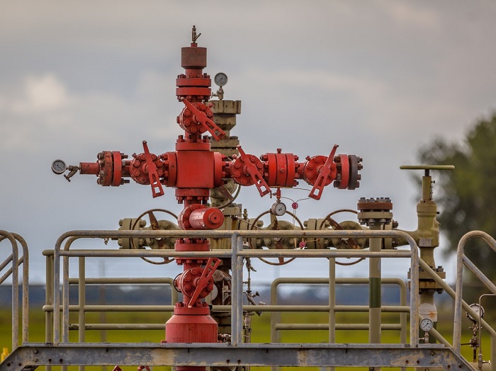
Introduction The wellhead is the top part of the well leading down to the reservoir. Oil from the reservoir comes out through the Well hole with casing. The oil or gas flow from the well should be sufficient to make it commercially feasible. Then only the wellhead is installed at the top of the well. It consists of valves and equipment that control the wellhead pressure and flow. That equipment and its control are the most crucial in oil fields. They avoid hazardous conditions in oil and gas plants. The hazard is caused by the flow of flammable materials out of the well and the high pressure inside the well. Thus, the flow through the wellhead must be controlled and made fail-safe. That’s why the Well Head Control Panels (WHCP) are employed. The wellhead is also known as the Christmas tree (because of its structure). The Christmas tree consists of the Subsurface Controlled Safety Valves (SCSSV), Surface Safety Valves (SSV), and other wellhead safety valves (Choke, ESD, HIPPS). These valves are used to close the well when needed. At the top of the tree structure, a pressure gauge will indicate the pressure in the tubing. Well Head Control Panel (WHCP) The purpose of a WHCP is to monitor the Subsurface Controlled Safety Valves (SCSSV), Surface Safety Valves (SSV), and other wellhead safety valves (Choke, ESD, HIPPS) for the safety of the well. A WHCP should prevent the risk of injury or damage to personnel, the environment, or equipment. Wellhead control systems are designed to be “fail-safe." The wellhead will be programmed and controlled by PLC or SCADA systems. The WHCP receives input signals from various gauges, including pressure, temperature, and flow gauges in the wellhead. In addition, the main inputs are from emergency shutdown systems (ESD), emergency pushbuttons, and fusible plugs. The output is generated by reading these signals, which is usually a command to shut down the valves on the wellhead to ensure the plant’s safety. The WHCP employs both hydraulic and pneumatic components. SCSSVs are mostly installed on land wells that are operated by hydraulic power. In that case, the WHCP must include a hydraulic reservoir and pump system to maintain pressure on the subsurface valves during normal operation. On the other hand, WHCP uses pneumatics for sensing and controlling surface safety valves (SSV). Christmas tree Components
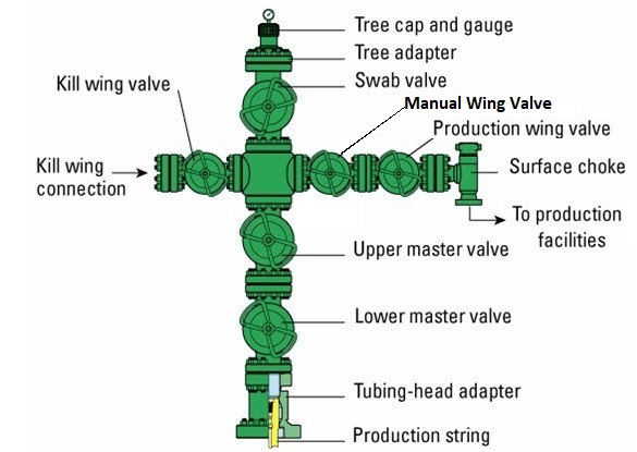
Figure 1 is a simple 5-valve Christmas tree, but there often exists much more complex setups. Most Christmas tree valves are custom made which makes it difficult to explain how all Christmas tree valves operate. This section will briefly explain the main components of Christmas tree valves and how they work to regulate the vitals of the well but understand that each Christmas tree works differently. We will go through the most important components of the Christmas tree valve labeled in Figure 2, to show how they work to keep a well productive. Lower master valve The lower master valve is a Gate Valve used to intercept the fluid in an emergency situation only. Upper master valve The upper master valve is a failsafe valve of the Christmas Tree, normally can be actuated by hydraulic or pneumatic. Kill wing valve The kill wing valve is another manual valve which is the connection point for injection. Fluids such as corrosion preventers, methanol, dehydration formulas, etc. can be injected via this valve. They are also known as side-arm valves or secondary wing valves. They are also used to inject drilling mud or cement to kill the well. This is the reason why is called "Kill wing valve." Manual Wing Valve Normally this valve is used during maintenance activities to guarantee double safety for those who carry out flowline maintenance Production wing valve The production wing valve, often located 180 degrees from the kill wing valve, is an automatically actuated component that requires positive hydraulic pressure to remain open. It prevents injection/flow to the well under emergencies or maintenance and is often paired with a choke to control flow volume and pressure out of the well. Swab valve + cap and gauge The Well Service Valve may be present on some Christmas trees, where Diesel pumping is required for initial start-up. It is on the other arm of the Christmas tree, and usually, the size is lesser than that of the wing valve. The valve at the top is called the swab valve and lies in the path used for good interventions like wireline and coiled tubing. A ‘Choke’ is a device, either stationary or adjustable, used to control the gas flow, also known as volume, or create downstream pressure, also known as back pressure. Sub-Surface Safety valve The Sub-Surface Safety valve is a hydraulic operated valve, the location of which is below sea level, above the sea bed. The actuator of this valve needs to be very small, as it gets enclosed within the Annulus of the conductor. The actuator is usually hydraulically operated. The control line for the hydraulic supply for the SSSV runs within the conductor and terminates at a connection on the Christmas tree. To open this valve requires at first equalising the pressure between the up and downstream of the valve then can be opened via hydraulic pressure. Without equalization, the valve even with hydraulic pressure applied cannot be opened, but it can be damaged due to large DP. Some valves are equipped with special flappers that in case the flow which passes through from it, is too high (maybe flow line damage) the valve will close, even with hydraulic pressure applied. Figure 2 below shows a typical SSSV Valve. The Wellhead valves are all controlled by a Well Head Control panel, which gives the hydraulic & pneumatic supply for opening/closing these valves. There is logically built in the WHCP for allowing the safe closure of all these wellhead valves, in case of an emergency, either due to process upset or due to emergency/fire. In addition to these valves, the other instrumentation which is associated with the Christmas tree is the Pressure gauges and Transmitters for monitoring the Annulus pressures, the Flowing Tube Head Pressure, etc. Wellhead Control Panel Philosophy Pneumatic circuits don’t have automated process control system, since the only operation required to restore the air collector pressurization shall be manually executed. Hydraulic circuit lines are pressurized by one of two automatic hydraulic pumps configured in a stand-by logic or, in emergency cases, by a manual pump. VHP circuit is fed by a pumping stage composed of two hydraulic pumps; LP and HP circuits are fed by another couple of hydraulic pumps. Pumps are in duty-stand-by logic, in order to switch one pump in operating state when the other is in failure or in maintenance condition. VHP and HP/LP pumps can be operated with local control panel, from which it is possible to select remote or local operating conditions. All the instruments transmitted signals are sent to PLC, which elaborates via software and applies the control loop actions stated for the specific control loop sequence. Some signals can be sent from PLC to DCS in order to view and modify the plant status. The Welldad control Panel. Hydraulic Control Panel Components
HP hydraulic Pumps HP Hydraulic Pump supplies the Surface Circuit which includes the Blader Cylinders compensation and supplies all Surface valves (Master and wing) through the solenoids for each Wellhead. The working pressure depends on which type of valve and Christmas tree are installed (the standard should be near 180 - 250 bar). Normally, the model are Variable Displacement Piston Pump as shown in Figure 3 below  Figure 3 - Variable Displacement Piston Pump
VHP Hydraulic Pumps
The VHP Pumm Supply the Subsurface Circuit which includes the Piston Cylinder (Compensation), and the SSSV Valves. The working pressure depends on wellhead static pressure (Normally, should be between 400 and 700 bar). Like all hydraulic circuits, the oil inside must be cleaned as much as possible and filtered to prevent metal waste from entering the pump, solenoids, or even into accumulators and maybe damaging them. The Most important are the SSSV's because metal slag in the hydraulic oil can break the valve. Figure 4 below shows a standard system of Hydraulic Control Panel
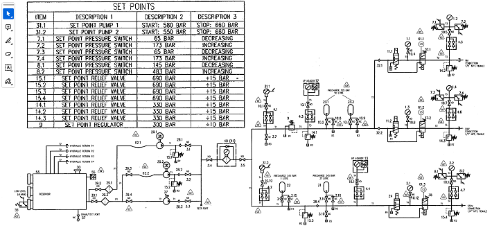 Figure 4 - Hydraulic Control Panel
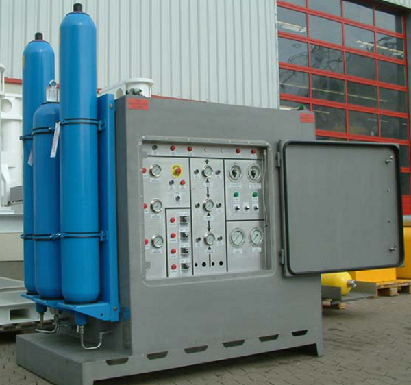
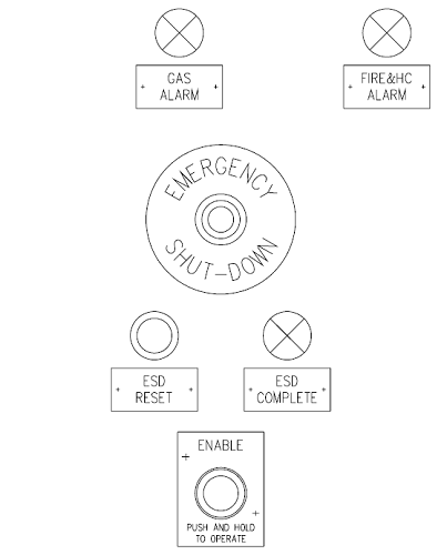
All control functions, indications, adjustments and alarms available at the WCP. This control panel is for a single wellhead. The figure below shows all the details.
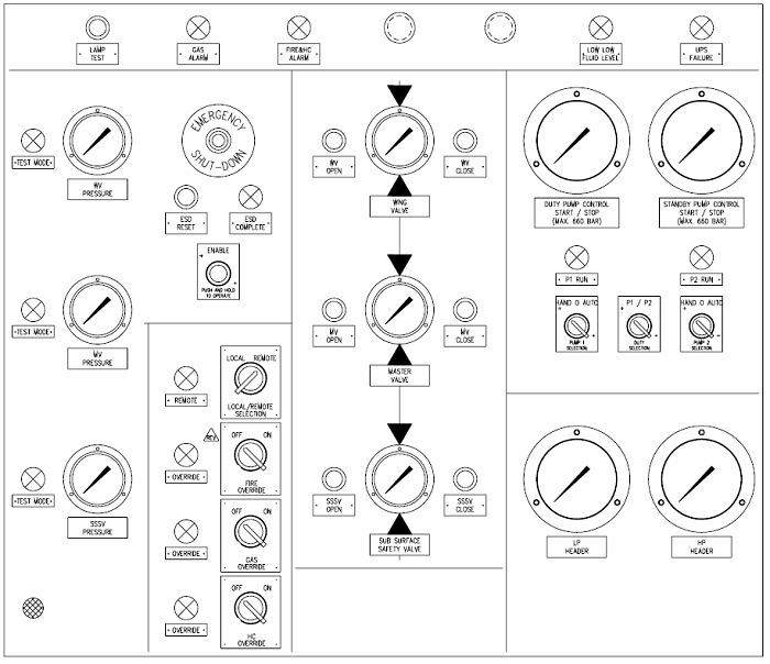 Figure 6 - Wellhead Control Panel
Hydraulic pressure generation
Two electrically driven pumps, controlled by the LCU via WCP located contact gauges, are installed to generate the required hydraulic pressure.
The pumps operate in a duty/standby mode. A selector switch is fitted at the WCP panel to allow the allocation of pump1=duty and pump2=standby or vice versa The WCP will be equipped with two contact gauges. The first is dedicated to the duty pump, the second is dedicated to the standby pump. Each pump has its own three-position selector switch with “Manual”, “OFF” and “Auto” are fixed positions, and “Manual” is a spring return position.
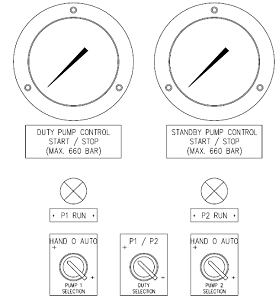 Figure 7 - Motor Pump Control at the WCP operator panel
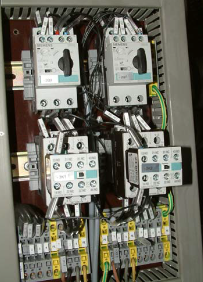
To protect the pumps of running dry they shall immediately be stopped if “low low fluid level in the reservoir” is detected. It shall not be possible to start the pumps if there is not enough fluid in the reservoir. Additionally, there should be a low-pressure pump stop. If the pumps are running in automatic mode and the pressure drops below 200 bar anyhow, they should immediately stop. This function shall be a protection against a line rupture or leak inside or outside the WCP. The pressure value to stop the pumps should be taken from the HP pressure Transmitter The pumps shall also stop if a “pump failure” is detected (e.g. motor starter released) Each pump has a dedicated “pump running” lamp at the WCP panel which indicates that the pump is running. In addition to the contact gauges, two analogue transmitters are installed in the LP and HP header lines to display the actual pressures at the remote-located Master Station. These transmitters can be used to generate low-level alarms for the Master Station. The motor starters and contactors will be located inside the WCP panel (see Figure 8)
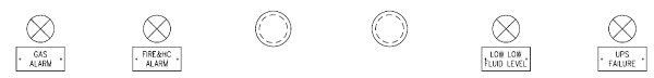
Alarm indication The WPC is equipped with alarm indication lamps and an audible alarm horn which will be controlled by the LCU. On detection of any alarm, the LCU shall alert the ESD system and activate the local audible and visual alarm system. The visual alarm consists of indication lamps located at the WCP panel (see Figure 10 )
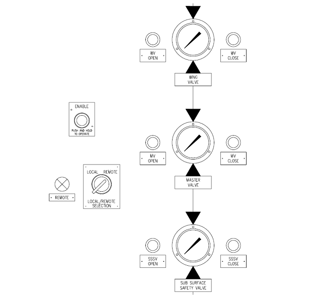
The audible alarm shall consist of two (2) tones: one for “H2S Gas” and one for “Fire and In addition, on detection of gas alarm or shutdown command, an external 21-joule Xenon Beacon shall be activated. This beacon shall remain active until manually reset at the WCP by pressing the “ESD Reset” button. Disappearance of an alarm condition shall switch between the visual and audible alarm as well as the alert at the ESD system. Operating the tree valves – SSSV, MV and WV The hydraulic dump valves inside the WCP, which will pressurise and depressurise the tree valves, will be controlled by solenoids. These solenoids are controlled by the LCU. To open and close these valves dedicated buttons at the WCP panel have to press together with the ENABLE button. The related PLC outputs will be energized to open the valve and de-energized to close them. Pressurisation of the output lines can be monitored by the dedicated pressure gauges. For remote monitoring of the open and closed positions of the valves dedicated pressure switches are located at the tree actuator output lines inside the WCP. Local control of the valves is only possible if the LOCAL/REMOTE selector switch is in the LOCAL position and the REMOTE indication lamp is off.
Open and closing of MV and WV are also possible from the remote-located Master Station if the panel is in “Remote” mode. Remote mode is active if the LOCAL/REMOTE selector switch is in the REMOTE position and the REMOTE indication lamp is on. Tree valves shall be operated in the order listed in the table below.
An Interlock is provided to prevent the operation of the SSSV while the MV and WV are open. Note: Interlocks are not operable during manual Override During manual Override function at the WCP. Emergency Shutdown functionality In case of an emergency situation, the LCU shall initiate a shutdown sequence to bring the Wellhead in a safe condition. The design shall ensure that the correct sequence as detailed below is provided for the Christmas tree valve closing.
A failure of any of the valves in a “shutdown” sequence, shall not prevent the other Shut down of the well by closing the WV, MV and SSSV shall be automatically initiated
After a shutdown sequence is initiated an “ESD active” signal shall be sent to the Master Station. If all three valves are closed additionally a “shutdown complete” signal shall be sent. To indicate the “ESD active” and “shutdown complete” at the WCP panel the “ESD complete” lamp at the panel shall flush while the shutdown sequence is running and illuminate constantly when the sequence is completed. Before it is possible to start up the well again the ESD request must be manually reset at the WCP panel by pressing the “ESD reset” button.
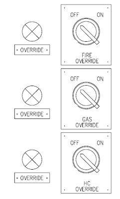
Confirmed fire detection will be achieved using two (2) heat detectors and two (2) UV/IR sensors. The shutdown command being derived from a two out of two voting system (2oo2) for each of them. H2S Gas detection will be achieved using three (3) H2S sensors pointed at the Wellhead. The shutdown command being derived from a two-out-of-three voting system (2oo3). Hydrocarbon detection shall be achieved using two (2) HC sensors. The shutdown command being derived from a two out of two voting system (2oo2) for each of them. Failure of a detector signal being voted as being equal to one. Local/Remote function The local/remote switch shall determine the centre of control for the Wellhead valves. With the switch in the “Local” mode, full control, with the exception of an ESD shutdown command, rests with the WCP. The Wellhead shall respond to an ESD Shutdown command, irrespective of the local/remote switch position. In addition, all alarms shall be transmitted to the ESD irrespective of the local/remote switch position. Reset after a shutdown shall be completed locally. The circuit shall be designed to prevent local manual operation of the SSSV, WV, and MV when “remote” mode is selected. To activate the Remote mode the switch has to be in the REMOTE position. The remote signal will then be transmitted to the Master Station. The Master Station acknowledges the Remote mode by sending the “remote mode acknowledge” back to the LCU via the serial link. After that, the REMOTE indication at the WPC turns on and the panel is in remote. In remote operation mode (i.e. DCS control), it shall be possible to command the MV and the WV to open or close. Maintenance override function To maintain or test Fire & Gas sensors and detectors dedicated override switches are foreseen at the WCP panel for Fire sensor override, Gas sensor override and HC override (see Figure 13).
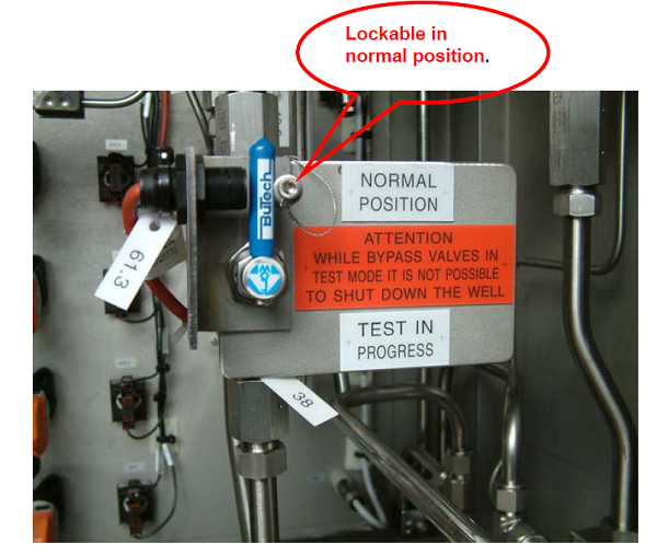
Maintenance overrides for the Fire & Gas detectors associated with a given WCP shall be “enabled” only if both the WCP override key switch and the appropriate ESD override enable switch, which is located on the Auxiliary Panel at the DCS, are both set to the “On” position. Setting these switches to the “On” position shall then allow the maintenance overrides to be activated via the Master Station by sending the “override acknowledge” back to the LCU. If the Local “override switch at the WCP panel is in the On position and the acknowledge is received from the Master station the override function is active and will be displayed by a dedicated lamp at the WCP panel. If the override function is active no shutdown sequences initiated by overridden sensors can be activated. Removal of an override key from a WCP switch shall cause the switch setting to revert to the “Off” position and immediately cancel the override to that WCP. Setting the override enable switch on the Auxiliary Panel to the "off” position whilst overrides are active, shall not cancel the overrides but it shall block the setting of further overrides. ESD test function For test purposes it shall be possible to by-pass the hydraulic dump valves associated with the closure of the SSSV, MV and WV, by lockable manual by-pass valves in the WCP (see Figure 14 - manual bypass valves inside the WCP Figure 14), to test the Wellhead shut down system. The test shall verify that all shutdown signals de-activate the Hydraulic Dump Valves, whilst maintaining the SSSV, MV or WV in the open state.
Indication of “test in progress” shall be indicated both visually and audibly at the WCP (see Figure 15) and Operator Workstation at the OTU. The local “test in progress” indication must be activated as soon as one of the bypass valves is in the test position.
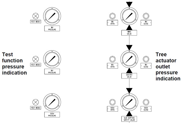
Figure 15 - ESD test section at the WCP operator panel Note: Interlocks are not operable during the manual override function at the WCP. To test the dump valves inside the WCP without full or partial closure of the well and therefore stop of production all three bypass valves must be in the bypass position. The bypass function will be indicated for each valve individually at the WCP operator panel If all three valves are in bypass a well shutdown can be initiated either from the panel, the field ESD or remotely from the DCS. Once the ESD is initiated the shutdown sequence starts and the solenoid valves inside the WCP will be de-energised. To verify that the valves are operating as required the pressure gauges are installed at the operator panel to monitor the pressure drop behind the dump valves. For a successful test, the pressure at the tree actuator outlet pressure gauges must remain and the pressure at the test function pressure gauges must drop to zero. After that test the ESD must be reset at the WCP and the solenoid valves must be energised again before the bypass valves will be put back to normal. Otherwise, the tree valve will be closed. To verify that the solenoid valves are energised again the test function pressure gauges must indicate full working pressure. A “successful” test of each shutdown shall be confirmed at the Operator Workstation at the DCS. On completion of the test, the system shall be manually reset and the by-pass valves padlocked in the “normal” position. Two hand operation To avoid unintentional activation of a function all operations carried out via WCP panel push buttons are two-hand operations. That means to operate the function the function button itself has to press together with the “Enable” button. Exceptions of this are the ESD and lamp test buttons. Conclusion The wellhead control panel is a very important part of the project, and for this reason must be robust and reliable. We always suggest purchasing panels that have already been tested on another plant like the one shown in this article. The choice of control software is also very important. For more information, you can contact our expert directly In conclusion, the wellhead control panel market is expected to experience significant growth in the coming years, driven by the increasing demand for oil and gas, advancements in technology, and the discovery of new reserves.
|
||||||||||||||||||||||||


+(39) 347 051 5328
Italy - Kazakhstan


09.00am to 18.00pm
About
We offer the best and economical solutions, backed by 27+ years of experience and international standards knowledge, echnological changes, and industrial systems.
Our Services
Marketing Materials


Marketing Materials1


