
|
Car battery charger with Temperature Protection
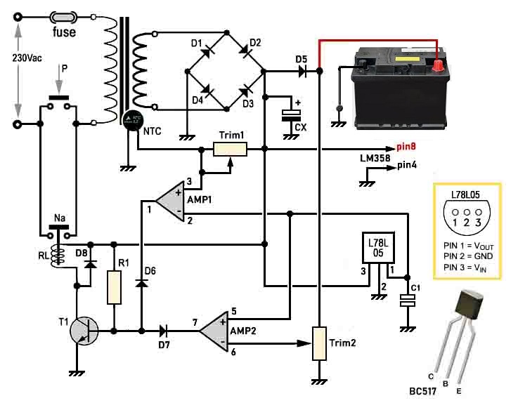
This is a simple car battery charger circuit with indication. The battery is charged from a 230V, 50Hz AC mains supply. This AC voltage is rectified and filtered to obtain an unregulated DC voltage used to charge the battery through a relay. This battery voltage is constantly monitored by a feedback circuitry compromised of a potential divider, a diode and a transistor. The relay and the feedback circuitry are fed by a regulated DC voltage (obtained using a voltage regulator). As battery voltage increases beyond the maximum, the feedback circuitry is designed such that the relay gets switched off and battery charging ceases. Figure below shows the drawing
Shutdown relay when charging the battery is complete In detail, we note that the relay is controlled by the transistor T1, brought into conduction via resistor R1. At the base of T1, there are also two diodes (D6 and D7) which come from the outputs of the operational amplifiers Amp1 and Amp2. These two operational amplifiers are part of the LM358 integrated circuit, each with its own function.
Amp1 Amp1, controls the temperature of the transformer, via the NTC thermistor, mounted in close contact with the transformer itself (very important, mandatory). If the temperature becomes excessive, the NTC value decreases, and with it, the voltage on the (+) input also decreases; the output therefore switches to a low level, blocking the conduction of transistor T1 with the consequence that relay will de-energized (opens the Na contact), disconnecting the appliance from the mains. The NTC should have a value of no less than 5 kohm; the value of Trim1 must be chosen based on the NTC, and its value must be one and a half times that of the NTC (for example, if the NTC is 10 kohm, a trimmer of approximately 15 kohm will be used) Amp2 AMP2 reads the voltage on the battery; when the value of the battery charge is considered complete, the operational switch switches to a low level and, as in the previous case, disconnects the device from the mains. It is therefore a rather versatile battery charger, which everyone can calibrate as they wish, with a little patience. List of components
Project cost The cost of the project without the automatic charger battery would be around 40$, while the automatic charger would be around 50$. For any questions contact our expert.
|


+(39) 347 051 5328
Italy - Kazakhstan


09.00am to 18.00pm
About
We offer the best and economical solutions, backed by 27+ years of experience and international standards knowledge, echnological changes, and industrial systems.
Our Services
Marketing Materials


Marketing Materials1


