
|
Excellent battery charger with SCR diode
In the digital age we present you an entirely analogue battery charger useful for charging 6, 12 and 24 volt batteries. This charger controls the charging current with two SCRs, which are finely driven by the logic around their Gate. A string of LEDs indicates the charging status. This ptoject Include:
Theorically, a charger for lead-acid batteries must perform the following function: supply electrons to the battery, so that the lead that has bounded to the sulphur wich is present in the sulfuric acid forming lead sulphate during the discharge reaction (i.e. when it provides energy), returns in the form of lead dioxide on the plates element. To rectify an alternating current, a diode bridge is normally used, also called, after its inventor, a Graetz bridge. It is a bridge made up of four diodes, which perform the function of rectifying a sinusoidal voltage to make it suitable for powering any load designed to operate with DC power (see figure 1). In this case, we have developed a "sui generis" Graetz bridge, where, like all bridges suitable for the rectification of alternate voltages, two diodes and two SCRs are used. SCRs are simply diodes with a gate, the Gate, which controls the current that passes between the anode and cathode. As you can see in Figure.2, instead of two normal silicon diodes, we used two SCRs. Practically, the SCR controll the power delivered.
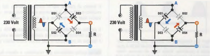
FIgure 1 - Operation diagram of a bridge rectifier. When the positive half-wave is present on A and the negative half-wave on B, the diodes DS2-DS3 conduct, vice versa the diodes DS1-DS4 conduct. A positive voltage always arrives on the load.
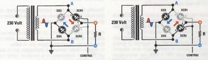
Flgure 2 - Operation diagram of our bridge. When the positive half-wave is present on A and the negative half-wave on B, they conduct DS4-SCR1, vice versa they conduct DS3-SCR2. In this configuration, the SCRs also control the charging current.
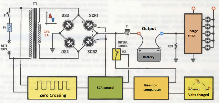
Figure 3 - Block diagram of the operation of our battery charger. The 50 hertz signal is taken from the network and sent to the SCR, at the point where the sinusoid goes from positive to negative and vice versa (0 crossing). The synchronism necessary for controlling the current charge according to the chosen charging voltage with a switch. Means the RCS resistor we measure the charging current moment by moment through the LED scale. The voltage is then perfectly regulated to the value of 15 volts by the time regulator of IC1. By means of the two photocouplers OC1-OC2 we take the alternating signal from the network, which we need to know when the voltage passes through 0 (zero crossing). This signal is cleaned and squared by the gates IC5/A-IC5/B-IC5/C-IC5/D and the resulting synchronism signal serves us, after crossing TR4 and IC2 and then TR1 and TR2, to synchronize and to check the power on SCR1 and SCR2 alternatively. Figure 5 below shows others components which required to pilot the SCR diode
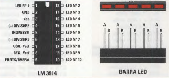
Figure 6 below shows the connections of the LM.3914 integrated circuit that drives 10 LED diodes in continuous scale mode or, as in this case, in point mode. Connections seen from the front and top of the 5-diode LED bar. The Anode terminal is always longer than Katodo terminal.
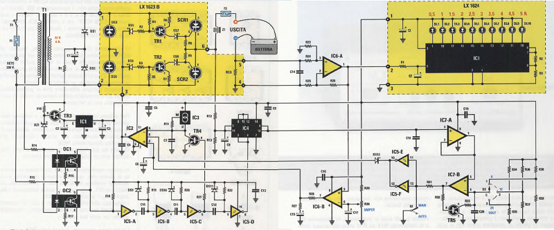
Figure 7 below shows the electrical diagram of the battery charger. Using the block diagram in figure 3 as a reference, at the top left there is the rectification bridge formed by the silicon diodes and the SCRs, at the bottom there is the 0 crossing detector, in the center the SCR control and the switch IC4, at the bottom right the comparator and at the top right the LED ammeter
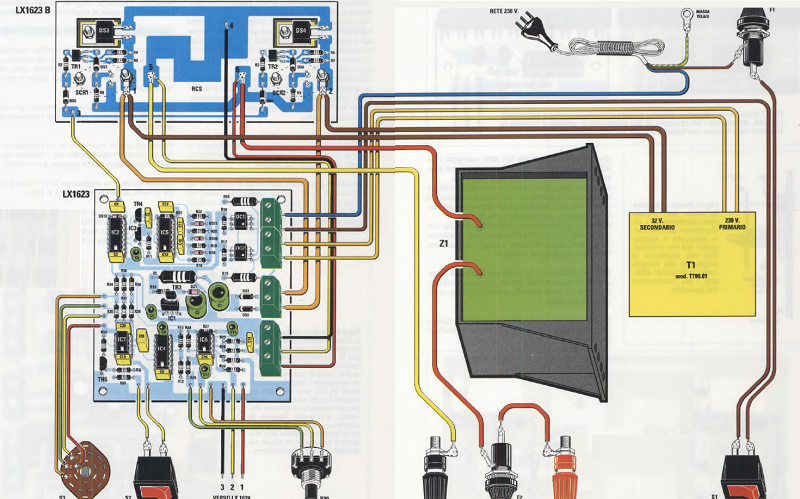
Figure 8 shows the practical diagram of battery charger monitoring. The large, almost life-size inductor Z1 should be assembled last.
Conclusion Look at the newly finished battery charger and compare it with the commercial ones: well there is no comparison, this battery charger is still the best ever. Regarding PCB boards please contact our expert. Available also the new model (available here) with an Microcontroller and display. Availble also for Electrical car If we look at certain tools sold by people who do anything but good business, a lead-acid battery charger may seem like a banal tool.
|
||||||||||||

+(39) 347 051 5328
Italy - Kazakhstan


09.00am to 18.00pm
About
We offer the best and economical solutions, backed by 27+ years of experience and international standards knowledge, echnological changes, and industrial systems.
Our Services
Marketing Materials


Marketing Materials1


