
|
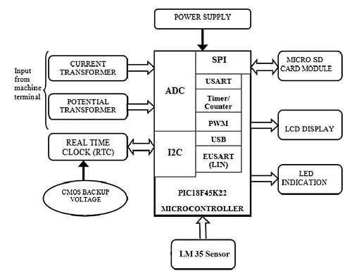
PIC and SD Card communication- using SPI and I2C Protocols for Industrial Applications The low-cost micro SD card-based Data Logging System (DLS) for the measurement of parameters such as temperature, load current, load voltage and power have been designed and developed. These parameters are the time-varying signals that are sensed by respective sensors. The sensor values are read by on-chip ADC and it is used for further process. The microsecured digital (SD) card is interfaced with PIC18F45K22 microcontroller in the Serial Peripheral Interface (SPI) mode of the Master Synchronous Serial Port (MSSP) for DLS design. The RTC is also interfaced with the microcontroller using I2C protocol to provide time stamping. The designed DLS has been tested with the application program developed in MPLAB X IDE which can write data into SD card at the rate of 5 samples/second. Introduction The term ‘data logging’ can be defined as the capture and storage of data for use at a later time. Basically, a data logger is an electronic device that is capable of capturing and recording data over time [1, 2]. Modern data loggers are based on microcontroller technology which is usually portable, battery-operated devices with internal memory storage and some interfaced sensors to measure physical quantities such as temperature, pressure, flow, voltage and so on. Data loggers can be categorized into two groups: standalone data loggers and data-capturing data loggers. The data loggers that can work on their own are termed standalone data loggers. It does not depend on other external devices for data collection and storage. These data loggers have large amounts of internal non-volatile memories. They may also interfaced with real-time clock chips. The collected data can be saved in the memory with time stamping [3, 4]. Once the data collection period is completed the device is connected to a PC and the logged data are read from the memory device which helps the PC in analyzing the values offline. Data loggers that are used only to read the data are termed data-capturing data loggers. These devices do not store data in memory devices and are normally connected to a PC for displaying or storing the data. Either the offline or online analysis can performed on the collected data. Data capturing data loggers have the disadvantage of requiring a supporting device like a PC to store the captured data. In this work, we have designed the standalone data loggers with the help of the PIC18F45K22 microcontroller. Material and Methods The design and development of a standalone data logger needs the microSD card and RTC along with the microcontroller. The selection of microcontrollers should be given higher priority. This system requires two MSSP modules to interface microSD card and RTC, and not less than 32KB program memory to execute instructions at minimum instruction cycle. Therefore the PIC18F45K22 microcontroller has been selected for this DLS. The block diagram of the standalone data logger using PIC Microcontroller is shown in Figure 1. As shown the standalone data logger hardware includes a power supply, a current and potential transformer, an RTC, a temperature sensor, a microcontroller section, a microSD card module, and a display device. The current and voltage signals are acquired from the load by using current and potential transformers. The on-chip ADC is interfaced with the current and potential transformer to get the load current and load voltage from the machine. The ADC samples the current and voltage signals and converts them into digital form. The digital values are given to MCU for the power factor analysis. The LM35 sensor is used to sense the current temperature of the machine. A microcontroller of PIC18F45K22 with a crystal of 20 MHz has been utilized in the proposed system. The MCU is updating the LCD display by the temperature, voltage, current and power factor information. The readings can also be transmitted to a microSD card through SPI protocol for a regular period of time using RTC. The RTC is interfaced with MCU using the I2C protocol
Figure 1 - Block diagram of standalone data logger using PIC Microcontroller Power Supply The 230V mains AC voltage is reduced to 12V AC with the help of a step-down transformer. This AC voltage is converted into 5V DC using a bridge rectifier and a 7805 type 5V regulator which can deliver current up to 1A. Sensing Elements Current Transformer (CT) A current transformer (CT) is a metering electrical device that produces an alternating current (AC) in its secondary which is directly proportional to the AC in its primary section [5]. The main use of CT is to reduce the current through a line (load) when it is greater than 5 ampere. The output may be in the form of current or voltage. It is connected to the on-chip ADC of the PIC microcontroller. Potential Transformer (PT) A current transformer (CT) is a metering electrical device that produces an alternating current (AC) in its secondary which is directly proportional to the AC in its primary section [5]. The main use of CT is to reduce the current through a line (load) when it is greater than 5 ampere. The output may be in the form of current or voltage. It is connected to the on-chip ADC of the PIC microcontroller Temperature Sensor The temperature of the environment is measured using an LM35 temperature sensor which is widely used in most temperature-sensing applications [7]. The sensor produces analogue DC output voltage on its output terminal. It produces 10 mV for every degree centigrade of temperature. LM34 sensor is particularly used if we need temperature value in Fahrenheit. Timing Module The Real-Time Clock module is referred to as RTC. It is an important integrated circuit or device that will keep track of current time and date [8]. In a data logging system, the RTC module is used to give the precise time of the system for which parameter values are displayed. RTC module communicates through the I2C bus of the PIC microcontroller Display Circuit The Liquid Crystal Display (LCD) is a flat panel display that uses the light-modulating properties of liquid crystals (LCs) to display a character. The 4x20 character LCD board is used in this system. It supports both 4-bit and 8-bit modes [9]. Only 7 lines are needed to create a 4-bit interface: 4 data lines (D0 – D3), and three control lines (RS, R/W, and E). LED Indication The Real-Time Clock module is referred to as RTC. It is an important integrated circuit or device that will keep track of current time and date [8]. In a data logging system, the RTC module is used to give the precise time of the system for which parameter values are displayed. RTC module communicates through the I2C bus of the PIC microcontroller. Memory Device The SD card is a flash-type memory which is designed to provide high capacity, non-volatile rewritable storage in a small size. The memory capacity and speed are increasing all the time. The specifications of different types of SD cards are shown in Table 1. The SD cards are in three sizes: standard SD, mini SD, and micro SD cards. Micro Secured Digital (microSD) cards are the most widely used memory cards in the modern world due to its very small size and larger memory size. The functionality of SD card is based on MMC but it has an advantage over MMC because of having an optional encryption feature. Table 1: Different types of memory card
A standard SD card can be interfaced in two modes SD Bus mode and SPI Bus mode. In SD bus mode, all the pins of the SD card are required to communicate with the microcontroller unit. In SPI bus mode, communication with the microcontroller takes place with a chip select (CS), a clock line (CLK), a Data in (MOSI) pin and a Data out (MISO) pin. The following are the PINs of the SD card
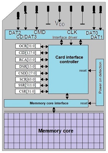
The architecture of the SD card is shown in Figure 2. The microSD card has been formatted as FAT32 before interfacing with MCU. The SD card only accepts the standard SD commands. Using these commands a MCU can read the SD card registers, and also read/write the memory core [11]. The most commonly used interfacing technique for SD cards is the SPI interfacing method. For the transferring of data in SPI mode a Data in pin, a clock pin, and a chip select line must be initialized. The card operates with a 3.3V supply voltage and the following are the maximum and minimum logic levels:
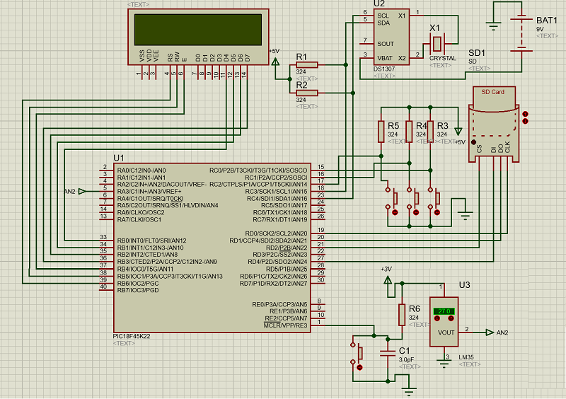
The maximum input logic of the SD card is only up to 3.6V but the logic high of the PIC microcontroller is 5V. So the voltage level should be reduced to the limit of the SD card using potential divider or regulator ICs. The output voltage of 3.2V of the SD card can be detected as logic 1 by the PIC microcontroller as a voltage above 0.8-5V is considered a logic high signal. SD cards can be interfaced to microcontrollers using two different protocols: The SD card protocol and the SPI protocol. In this system, the SD card is interfaced with the microcontroller using SPI protocol. The data are stored on a microSD card as a text file. The text file can be an existing one or a new one created by the user using developed application software. 2.6 PIC Microcontroller – The Central Unit The PIC18F series has a RISC architecture that comes with standard features such as on-chip program ROM, data EEPROM, timers, ADC and advanced features like USART, MSSP, USB, CAN etc [12]. The PIC18F45k22 Microcontroller works on a 16-bit instruction architecture. The PIC18F45k22 Microcontroller consists of USB, two USART modules, CAN, and LIN (using EUSART) and two MSSP modules that can support communication protocols like I2C, SPI, etc. The circuit diagram of the microcontroller and SD card-based standalone data logging system using SPI and I2C protocol is shown in Figure 3. The PORTA pins are made as analogue input by using the ADCON1 register. The PORTB pins are used to interface the LCD unit in 4-bit mode where the LSB (0-3) bits act as DATA lines and MSB (4-6) bits act as control lines. The MSSP1 module signal lines are multiplexed with PORTC pins and it is used to interface the RTC module in I2C mode. The MSSP2 module lines are multiplexed with PORTD pins and it is used to interface the microSD card module in SPI mode. The LSB (0-2) three bits of PORTC are used to set the time for the RTC module according to the region.
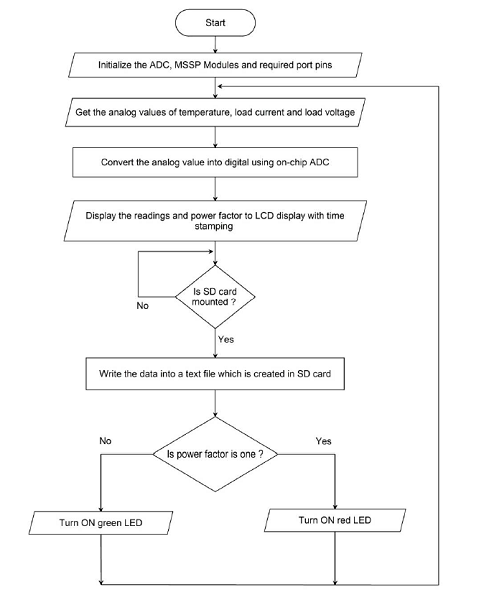
Software Design The software section of the system is developed using MPLAB X IDE. This version has the most advanced features like driver switching, code generation for particular modules of specific series and so on. The MPLAB X IDE also comes with MPLAB IPE that comes in the programming of the microcontroller from the IDE window. The XC8 type of compiler is used to compile the given C coding to binary data [13]. Figure 4 shows the flowchart of a standalone data logger using a PIC Microcontroller. The software design and development for a standalone data logger using a PIC Microcontroller can be done by enabling the MSSP and ADC modules of PIC18F45K22. The ADC module is programmed to read a sample on every 100ms cycle and it is taken for analysis. The MSSP1 module is set in I2C which provides a clock and data line for the RTC module. The MSSP2 module is set in SP1 mode and it is used to write the data into a microSD card only when it is mounted to the module. If the microSD card is not mounted the program will not enter into data write operation. The current and voltage signal values are introduced in the MCU from the load by using CT and PT. The microcontroller calculates the phase angle between current and voltage signals by measuring time intervals using an on-chip timer. Using the power factor formula the MCU calculates the power factor. If the power factor is equal to one, the red LED is turned ON otherwise the green LED is ON.
The data logging system is an invaluable tool to capture and analyze the data. It can clearly present real-time data fetched from sensors and probes. The above system is implemented to monitor the various parameters like current, voltage, power factor, and temperature consumed by a machine for processing a material in an industrial application. By realization of the system, one can acquire knowledge of embedded systems and metering devices.
|

+(39) 347 051 5328
Italy - Kazakhstan


09.00am to 18.00pm
About
We offer the best and economical solutions, backed by 27+ years of experience and international standards knowledge, echnological changes, and industrial systems.
Our Services
Marketing Materials


Marketing Materials1


