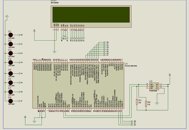
PIC24FJ128 with EEPROM and LCD Display

 pic24 eeprom display

The circuit is almost the same with PIC24 and LCD, the only difference is that the PIC24 and LCD use the internal memory of PIC24, while this circuit uses an external memory, in this case, 24C512.
The PIC24 (master) usually control the bus. The PIC24 send a start bit following with the address of the slave, and also the bit if required to write or read the slave, (24C512). Then muster sends the address of the EEPROM where data are located, then in sequence will send a repeated start followed with slave address again, then the EEPROM will send all data from this point until muster decides to stop

As usually the function of the display is to convert the binary format into ASCII characters. The series of LEDs on the left represents the binary output before being into the LCD, and are driven by the microcontroller via the PORTBs.

For more details see the sequence below

  1. Start Sequence from Master
  2. Master sends device address for writing
  3. Muster Sends the register address where the data is located
  4. Repeated start sequence
  5. Muster Sends the peripheral address for reading (bit zero of the address set to 1)
  6. The Slave sends the value (the value will be contained in the SSPBUF register)

Figure below shows all step comunication

eeprom random read

The entire routine is in assembly and you can download it here


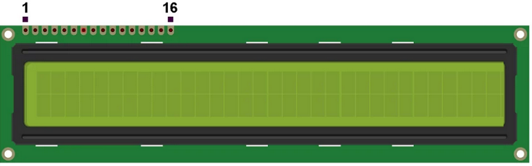
Controller LCD pinout

32LCD

The 32×2 display has the pinout as described below:

  1. VSS: Also known as GND (ground), it is the ground connection of the LCD module
  2. VDD: Also known as VCC it is the power supply positive terminal of the module
  3. V0: Also known as VEE, this pin is used to control the contrast of the display, it is usually connected to a potentiometer or variable resistor output
  4. RS (Register Select): Selects whether data is being sent to the display as a command (instruction) or a display data. A logic low for command and logic high for display data
  5. R/W (Read/Write): This pin selects whether data is being read from the display or written to it. Logic high for Read operation and logic low for Write operation. If just write operations are required then this pin could be connected directly to GND
  6. E (Enable): A pulse input to the enable pin triggers the Read/Write operation of the display whatever it is a command or display data
  7. 7 -10. DB0 to DB3: Four low-order bidirectional data pins are used for data transfer between the microcontroller and the LCD. These pins are used only in 8-bit operation and they are not used in 4-bit mode.
  8. 11-14. DB4 to DB7: Four high-order bidirectional data pins, used for data transfer between the microcontroller and the LCD
  9. 15. A (Anode): This pin is the anode terminal of the backlight LED
  10. 16. K (Cathode): This is the cathode terminal pin of the backlight LED

favicon bacd

+(39) 347 051 5328

Italy - Kazakhstan

09.00am to 18.00pm

About

We offer the best and economical solutions, backed by 27+ years of experience and international standards knowledge, echnological changes, and industrial systems.

Marketing Materials

Spring Renovation
Industry
US Gas Company
Construct
Plus Project
Vam Drilling Service
X Project
X Project
Cabrrus Training

Marketing Materials1

Spring Renovation
Industry
US Gas Company
Construct
Plus Project
Vam Drilling Service
ultrasonic sensor
ultrasonic sensor
Cabrrus Training