
|
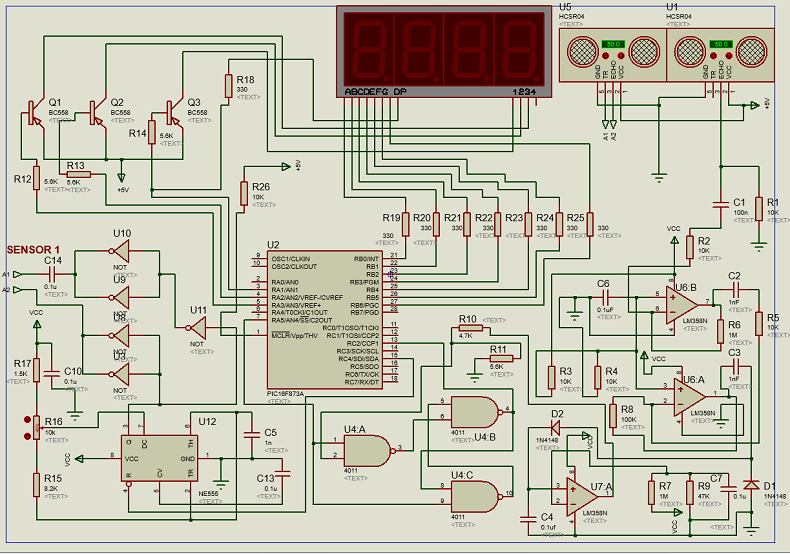
Circuit 147 - Ultrasonic Distance Meter Circuit with PIC16F873
This application note describes the implementation of a meter away, using ultrasonic sensors of the type-R40K1 UCM. A gust of 40KHz is transmitted through an ultrasonic sensor, the reflected ultrasonic sensor is greeted by another receiver.The calculation of the distance is done with a PIC16F873. The range of distance is measured 25cm to 300cm. Circuit characteristics
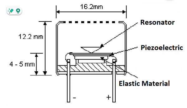
Ultrasonic sensor Ultrasound refers to frequencies above 20KHz (limit of audible sound). High frequencies have short wavelengths which means they can be read when reflected off objects. Unfortunately, very high frequencies are difficult to generate and read. The generation and reading of ultrasound is done through two piezoelectric units where one of them is the emitter and the other the receiver of ultrasonic pressure waves. For this, the transmitting unit must be excited with a signal adequate in amplitude and frequency. The receiving unit will transduce all those 40KHz ultrasonic pressure waves that excite it. Ultrasound is commonly applied in motion detectors, distance meters, medical diagnosis, cleaning, non-destructive testing (to detect imperfections in materials), and welding, among others.
Figure below shows all details regarding internal Parts of sensor
Ultrasonic Distance Meter
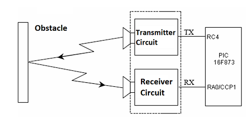
The distance is calculated by reading the time it takes for a reflected ultrasonic wave to return. Ideally, the obstacle should have a large cross-section and not absorb ultrasound. The most used method for determining distance is to send trains of 40 KHz pulses with very short periods. The time elapsed between the beginning of the emission and the beginning of the reception will be proportional to the distance travelled by the ultrasonic waves. As the echoes must travel a greater distance, they will be received by the receiver a period later than the direct waves, and will not disturb when quantifying the distance. Figure below show all details
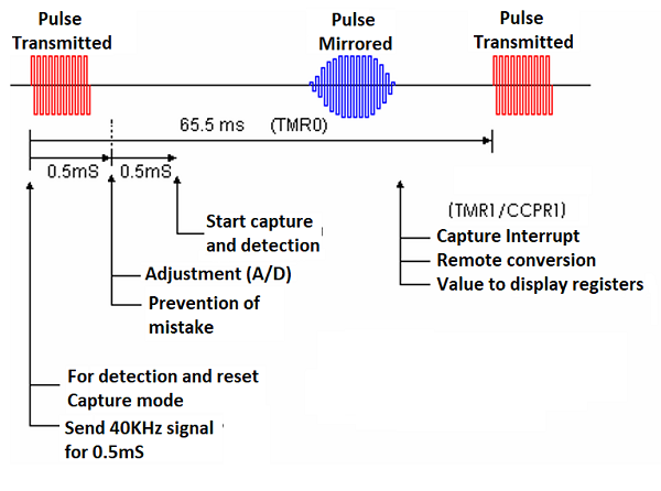
Functioning If a signal of 40 KHz with a duration of 5 mS is generated every 65 mS. Upon detecting the reflected wave, an interrupt is generated which stops a 16-bit timer. For more details see Figure below
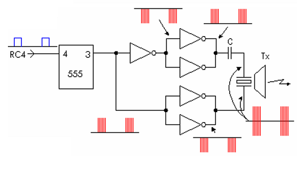
To calculate the distance, we know that the speed of sound is 343m/s = 34300cm/s (at 20ºC), therefore: 1cm= 1sec/34300cm = 29.15us To calculate the distance, divide the timer value (fosc = 4MHz, value equal to 1uS) twice by the time of one centimetre. Total time of the reflected wave = 3887us. The distance between the sensor and the object: (3887us/2)/29= 67.017 cm. The division by two is because it is considered that the wave when reflected travels twice the distance from where it was emitted. Transmitter The transmitter is built with a 555 and CMOS inverters, the CMOS feature is used to put them in parallel and increase the transmission power. The signal coupled between the positive and negative terminals is 180º out of phase, so the voltage applied between the terminals is double. For more details see Figure below
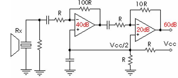
Receiver The receiver is composed of two circuits: a signal amplifier and a detection circuit. The signal is received by the receiving sensor and amplified 1000 times (60dB) in two steps an amplifier for 100 (40dB) and an amplifier for 10 (20dB). See Figure below
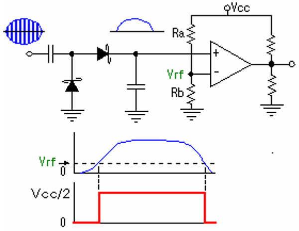
The signal detector consists of a half-bridge rectifier and a comparator. The comparison voltage is set at 0.045Vdc. See Figure below
For further details see the PDF attached here For the assembly source code click here
|

+(39) 347 051 5328
Italy - Kazakhstan


09.00am to 18.00pm
About
We offer the best and economical solutions, backed by 27+ years of experience and international standards knowledge, echnological changes, and industrial systems.
Our Services
Marketing Materials


Marketing Materials1


