|
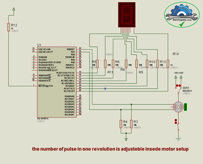
Circuit 156 - Reading an incremental encoder with single display and PIC16F877
An encoder is a device that converts the angular position or motion of a shaft or axis into an analogue or digital code. They are commonly used in the industrial, on automatic machines to control motors and movements, positioning and adjustments.
We have numerous types of encoders based on their operating modes, coding systems and output signals. Mainly we can divide them into absolute encoders and incremental encoders.
Absolute Encoders, provide the angular position immediately and retain it when the power supply fails; this requires a fairly complex construction and a certain number of output pins to be able to read the encoding. These are high-precision, but expensive devices.
Incremental encoders, on the other hand, provide a pair of pulse outputs, normally on square wave between each other (two input) and from the analysis, the logic which they are connected must find the position, direction and speed of the shaft.
There are models that use optical or magnetic sensors; these are usually devices of a certain cost (several hundred euros) and with high characteristics (even 10k pulses per revolution and rotation speed of 30krpm), suitable for integration into automatic machinery and robotics.
However, there are other models, like those made with mechanical contacts that are not intended to be rotated by mechanisms, but rather, to be operated manually, by acting on a knob, similar to a potentiometer. This destination means that they have a low number of pulses per revolution (from 4 to 24) and a low maximum rotation speed (60-120rpm), which, together with the construction technology, make them very low cost objects (<€5) .
For more details see Figure 1 below
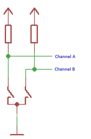
Figure 1 - channels one and channel two
They are used intensively as input devices for digital systems, from instrumentation to audio equipment, where, for example, they replace analogue potentiometers. The angular movement is interpreted by the microcontroller and transformed into the PWM or voltage variations necessary for regulation.
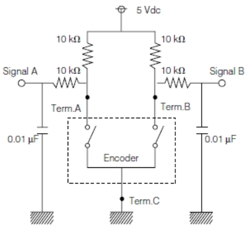
Constructionally, the encoder contains two sliding contacts on suitably shaped tracks that open and close between a common terminal and two outputs A and B.
These outputs, equipped with pull-ups (resistors), are connected to the I/O of the microcontroller. The sequence of openings and closings that are determined by the rotation allows the software to process the information.
It should be noted that, despite appearing in many examples on the WEB, using weak pull-ups integrated into the chip may not be a good solution. In fact, if you use these, you save two external resistors, but we are dealing with mechanical contacts, which require a minimum current to function correctly. The WPUs have quite high values (70-100k), while the datasheets generally indicate the need for a pull-up of 10k on average.
Use with currents that are too low causes uncertainties in switching, especially after a certain amount of use.
From a logical point of view, the relationship between signal phases to determine the direction of rotation. As seen in the diagram in Figure 2 below.
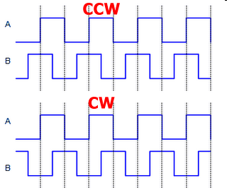
Figure 2- Direction sequence
- If the rising transition of B precedes that of A, the rotation is counterclockwise (CCW - CounterClockWise).
- if A precedes B the rotation will be clockwise (CW - ClockWise)
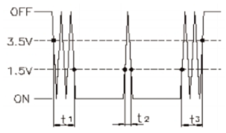
The interpretation of the signals is developed by considering the pulse transitions. There are several ways: the one we see now is based on one consideration. For more details see Figure 3 below
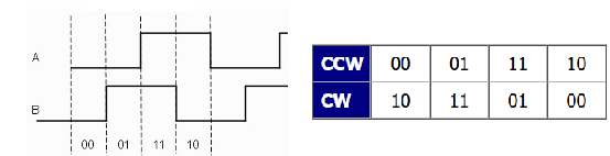
Figure 3 - Square Waves
Let's observe from Figure 3 above how the superposition of the two square waves determines 4 phases in a cycle
It is, in practice, a two-bit Gray code, in which only one-bit changes at each transition.
We can analyze the situation by synchronizing with one or more switching edges through an I/O interrupt (INT) and checking with a lookup table. However, Baselines do not have this function, so you can resort to polling the I/O. Furthermore, we can also process variations of the Gray code from time to time.
First of all, we can easily determine whether state changes have occurred in the signals: if we take an image of the signal logic levels and then compare this with the current situation through an XOR, a change is indicated with a result other than 0.
If there has been a change, we perform an XOR between the previous situation, shifted to the left by one position, and the current one; each pair of values for CCW movement will be 0, while CW will be 1
For each variation, the program will derive a pulse in one of the two rotation directions, allowing both an up/down count and the detection of the angular position, evaluating the relationship between pulses per revolution and rotation angle. Furthermore, it is possible to detect the speed by calculating the period of the pulses and, consequently, also acceleration or deceleration.
It should be kept in mind, however, that encoders with mechanical contacts are subject to bounces during switching; given that bounces take up much longer than an instruction cycle, it is necessary to prevent the program from interpreting these events as valid signals.
Furthermore, since they are rotated by hand, some irregularities (chattering or slippage) are possible during the rotation, which, if not considered, would distort the count. Figure 4 below shows just this
Figure 4 - Bounces during switching
The datasheet states 3ms maximum bounce and 2ms for any noise during rotation. These are maximum values that are difficult to find on a new component, but possible after a long working time, with the wear of the contact surfaces.
A technique to correct the situation is to check the encoder status every 1/(resolution*max. revolutions_per_second). Thus, a 24 pulse per revolution encoder with a maximum capability of 120rpm (1 revolution per second), will be polled every 1/24*2 = 20ms. We have said that these are encoders rotated by hand, acting on a knob and that the nominal value of 120rpm reported on the datasheet is very difficult to reach, in practice, so we can rely on much lower values. In this direction, it may be useful to know that the larger the diameter of the knob, the lower the possible rotation speed and therefore the lower the need for sampling.
On the other hand, if you have fast enough processors, you will be able to do much faster sampling or use I/O interrupts to check the switching edges on which to apply algorithms to isolate disturbances. This may be burdensome or not feasible for low-end microcontrollers: the burden of the program with the addition of complex software debounce can be avoided by inserting an RC network that reduces or cancels the bounces:
The circuit is recommended by Panasonic for its EVE series mechanical encoders and is suitable for virtually all models.
The pull-ups are 10k and, between these and the PIC input, RC low pass filters are inserted consisting of another 10k resistor and 10nF capacitor.
The values are not critical: resistors can vary between 4k7 and 47k and capacitors go up to 100nF. The higher the values, the greater the noise rejection, but the worse the switching edge will be, which requires a chip input equipped with a Schmitt trigger. In particular, the pull-up value recommended by manufacturers varies from 4k7 to 10k (and similar): a reading of the component datasheet allows the most suitable choice. For more details see Figure 5 below
Figure 5 - Panasonic Circuit pull-up Circuit
Detent
Most of the mechanical encoders intended for manual operation with a knob are equipped with detents: these are simply mechanical stops that advance the rotation in jerks, with the typical click. This solution makes the operation of the knob sensitive to the user and, at the same time, stops it in specific positions. This does not penalize the use of the encoder: we have seen that for each cycle the two signals allow 4 different positions to be determined. For example, if the encoder takes 24 steps per revolution, there are 15° between one step and the next; by detecting the intermediate codes, we can identify shifts of 15/4=3.75°. This is called "4x resolution" and can be useful for better defining positionings made by servo controls.
However, in manual operation, the encoder replaces a switch or an enhancement in a field other than positioning and too high a definition would become counterproductive, due to the uncertainty due to manual operation. Furthermore, there would be the possibility of backslash, that is, when the knob is released, one or more clicks backwards in the count. The detents, usually in numbers equal to the resolution of the encoder, avoid all this, as well as providing the user with clear rotation feedback; the detent becomes indispensable in the presence of vibrations, as in the case of automotive equipment. The definition of variations other than those of the nominal resolution can still be carried out by the management program, but they are not useful in practice except to increase the ratio between a step and the number to be counted or to determine acceleration or deceleration of the rotation.
The model without Detent has continuous rotation similar to a potentiometer and allows the software to implement either 4x resolution (one count for each change), 2x (one count every two changes) or 1x (one count every cycle).
If the models with detents are preferred to give tactile feedback to the user, very practical in consumer devices, the models without detents find their place on audio and video equipment panels, where they replace the classic analogue potentiometers. We also find them as instrument adjustments, where they require greater resolution - although here, to a large extent, it must be considered that these are optical and not mechanical encoders, given the problem of contact bounces, the correction of which becomes more difficult with the ' increase the resolution. For more details see figure 6 below
Figure 6 - Dente Encoder
Detent models can have different ratios between pulses per revolution and detents per revolution; for example, here are some models from the Alps catalogue:
| Model |
EC11B15202AA |
EC11E09244AQ |
EC11E1830401 |
EC20A1824401 |
EC12E24204A7 |
| Pulses per revolution |
15 |
9 |
15 |
20 |
24 |
| Detent per revolution |
35 |
18 |
-- |
20 |
24 |
Furthermore, not everyone operates in the same way, even if the tendency is to have open contact with the detainee; this allows for minimal consumption if the shaft does not rotate.
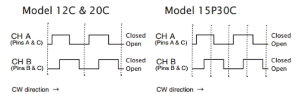
Encoder CUI. la Figura 7 sotto mostra l'immagine a sinistra si riferisce a modelli con 12 e 20 impulsi e detent per giro. Quella a destra si riferisce a encoder con 15 impulsi e 30 detent.
Figure 7 - Encoder CUI
Knowledge of these elements is necessary if you want to implement interrupt- and table-based decoding algorithms or where acceleration detection and similar extra performance are required.
In general, the choice of encoder type will depend on the application; High resolutions or rotation speeds are not necessary for manual adjustments. In our case, where the analysis of quadrature signals is carried out by a Baseline, without interrupts, and with a simplified procedure, we can use a very economical mechanical contact model with detent equal to the number of pulses, to have a positive feedback immediate between the rotation and the variation of the processed count.
The program for this circuit is entirely written in assembly. The microcontroller as seen in the first figure above is a PIC16f877, but it is possible to use other types of PIC without any problem.
The main program consists only of a loop with the calling of the various subroutines:
; counting loop
countloop:
call Dly3msT0 ; 3ms cadence
call Chck_Encoder ; check encoder and update counter
movf counter,W ; recover counter
call Segtbl ; convert number->7 segment mask
call Display ; to the display
goto countloop
The encoder test is carried out at a cadence of approximately 3ms, which allows a debounce action. The time routine is one of those already seen in the Tutorials, using Timer0 preloaded with a specific value and waiting for overflow.
The encoder status check routine detects the last value of the inputs and saves only the bits of the two channels:
;-----------Check_Encoder----------------
; Check encoder status and update counter
;Check_Encoder:
movf encoderport,W ; reads encoder
andlw b'00000011' ; mask only useful bits
movwf attuale ; and save
An XOR with a copy of the previous value allows you to determine if there has been a change:
; If the current reading is the same as the previous one
; there was no change.
previous xorwf,W
skpnz ; if different, skip
retlw 0 ; equal - returns
In this case, the routine shifts the previous value one position to the left, injecting a zero to bit 0 via carry. This aligns the LSB with bit 2 of the current value. The XOR of the two determines the direction and therefore whether the counter increases or decreases.
; Shift read bits left for xor
clrc
rlf precedente,F
; XOR current state with the previous one shifted
movf attuale,W ;
xorwf precedente,f
; Set outputs
btfss precedente,1 ; test bit 1
goto SetUp ; count Up
goto SetDn ; count Down
The counter is updated only every 4 valid pulses, i.e. equal to the encoder detents, with an equal number of pulses per revolution:
; Resolution x1
; - for each transition (4 per cycle) the direction is defined
; and a local counter related to the direction is decremented.
; - every 4 transitions the general counter will be changed
; ==================== Clockwise Movement ===========================
; Clockwise movement, check for 4 steps in the same direction
SetUp decfsz dirup,f
goto setendU ; n - exit for now
incf counter,f ; s - increment counter
goto EndPulse ; end of procedure
Similarly for Down counting. If you want to increase the resolution, you can change the value of the step constant:
| STEP |
variations on the counter |
| 4 |
1 per cycle |
| 2 |
2 per cycle |
| 1 |
4 per cycle |
Upon exiting the procedure, the local counters are updated and the current situation is copied into the previous one, for the next check:
endp movf attuale,W ; save current reading for
movwf precedente ; next test
retlw 0
The transformation of the LSB of the counter into the command mask of the seven segments is carried out with the lookup table as we saw in Exercise 5.
The division of actions into subroutines allows you to easily modify the program. Thus, for example, the presentation of the data on the display can be easily modified for different hardware.
It should be noted that the rotation identification method can be transferred to any other PIC without problems, given that everyone can execute the Baseline instruction set.
For any questions please do you not hesitate to contact us. To build this circuit, all components are available here on the website
|