
|
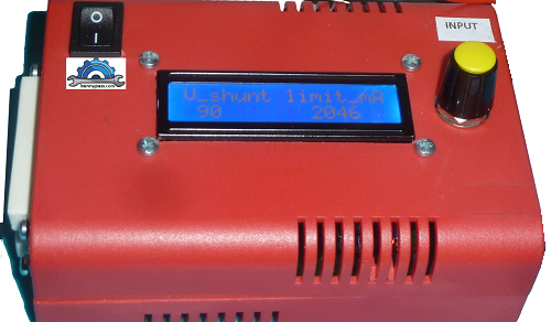
Delta Peak Charger for Nicd Nimh Battery with PIC16F86
Electronic Circuit
Control the battery charging circuit with PIC16F876 150 mA power in 6000 NiCd, NiMH batteries can be recharged with a power of 2 amps. The PIC output uses two MOSFETs (irf9540, IRF530) for the battery fast charging, also the voltage of 0.4 volts, which is under the battery for a shock, the recovery system has a circuit partially made easy but quite a detailed work plan there (Delta-Peak, PWM etc.) All information about recharging time, current consumption, life cell, etc, are shown in the LCD display. This device is not intended to constantly charge all the batteries in the household (it is too time-consuming for that). Rather, in addition to charging, it enables an analysis of the condition of individual battery cells or batteries (the remaining capacity is determined) as well as battery care. For more details click here Features of the charger The capabilities of this circuit are truly exceptional, below the descriptions
This device meets all these requirements. The goal is not to charge all batteries individually with this device, but rather to care for and measure individual cells. The heart of the circuit is a PIC16F876, equipped with an LCD display (1x16) and rotary encoder on PortB or via RS 232. PortA is used to measure voltage and PortC is used to control charging electronics. The PWM RC2 output is used to set the intensity of the charge/discharge current. The 16F876 is built on a universal controller board, the base of the 16F876 and connections for the 16F876 are on a 75 x 100mm board. Also available is an RS232 (MAX232) driver with Sub-D-9 socket and a voltage rectifier/stabilizer that allows the board to be powered by any 9V...15V AC/DC voltage source. A power supply supplies +5 V (Vdd - Vss) for the controller and charging electronics and an additional 12 V/2 A for the charging electronics. Precise stabilization of Vdd = +5V is required since this voltage is also used as a reference for the PIC's ADC. (It is not the exact adherence to the 5V value that is decisive, but rather its consistency. The PIC controls a constant current source that charges the battery at approximately C/3 and a discharge constant current sink that discharges the battery at C. (C is a current that corresponds to the battery capacity/h, e.g. 700mA for a 700mAh battery.) The constant current source for charging the battery is constructed with an OPV (LM358) that drives a P-channel MOSFET (IRF9540). It regulates the current so that a voltage drops across the measuring resistor R14 - 17 (0.47 ohms) that is identical to the voltage at the positive input of the OPV. By limiting battery capacities up to 6000mAh, the charging current is limited to a maximum of 2A in order not to overload the existing power supply. For more details see Figure below
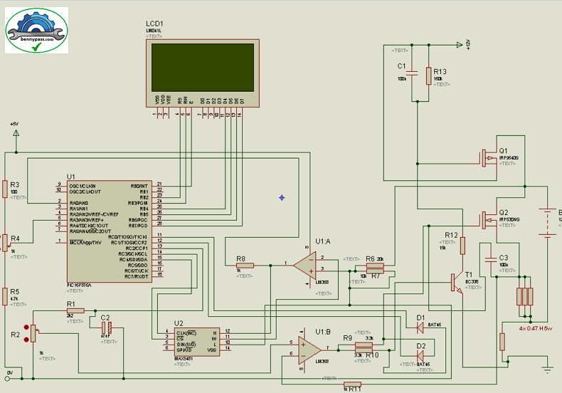
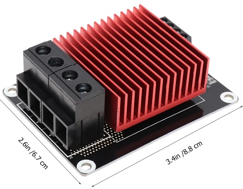
Figure 1 - Heat Sink for MOSFET (next generation) Figure 2 below shows the Electrical drawing of power Card
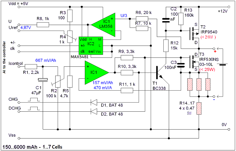
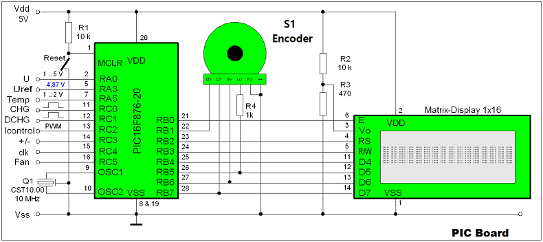
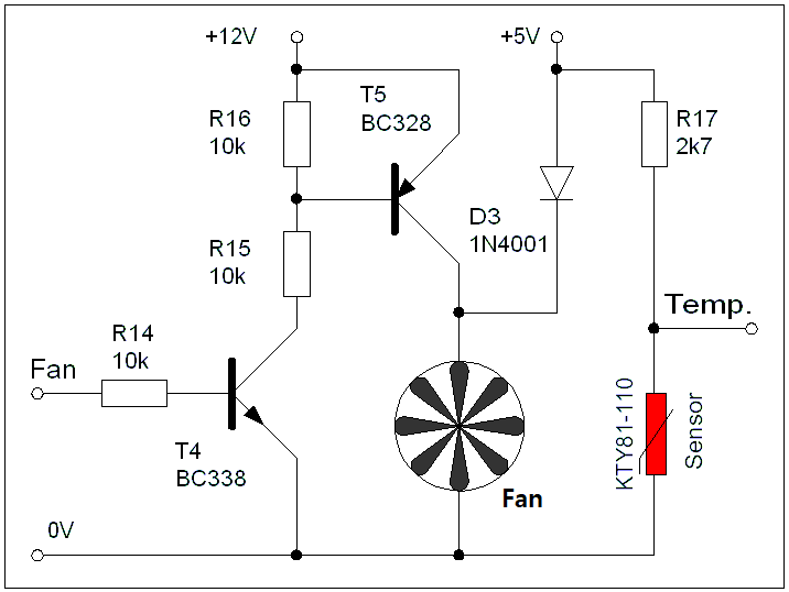
Figure 2 - Power Card The PIC control board is completely separate from the power board, for more details see Figure 3 below Figure 3 - Microcontroller board It is also possible to connect the heat sink to a cooling fan. the following figure 4 shows the fan circuit with its start-stop thermostat
Figure 4 - Cooling fan The discharge circuit is a constant current sink that uses the same OPV, but this time it controls an N-channel logic-level MOSFET (SMP60N03-10L), which discharges the battery via the measuring resistors R16..R18. It regulates the current so that a voltage drops across the measuring resistors (0.157 ohms) that is identical to the voltage at the positive input of the OPV. This guarantees that the discharge current is always three times as large as the charging current. Both the charging circuit and the discharging circuit are normally blocked by the PIC via D1&D2 and are only switched on when charging or discharging. The PIC sets the current intensity using the duty cycle of a PWM signal, which is converted into a DC voltage by R1&C1. The current intensity is adjusted once with R2. This comparison is supported by the software. Due to the high gain of the OPV, the power sources inevitably tend to oscillate. Suppression of the oscillations using a negative feedback resistor on the OPV is not possible due to the different operating points when charging or discharging. Therefore C2&C3 were used to suppress vibrations. The battery cell voltage is monitored using the PIC's ADC. An ohmic voltage divider (R6&R7) first divides the battery voltage into thirds. A downstream OPV with adjustable gain amplifies this voltage again. The gain factor G of the OPV is adjusted via an electronic 100 kOhm potentiometer (MAX 5481) according to the number of cells in the battery. The following applies: G = (100 / 14) / (8 - Z) Where Z is the number of cells in the battery pack. This means that 2.381 times the single cell voltage is present at the ADC input. By using a positive reference voltage of 4.8714V, the reading obtained by the ADC is half the cell voltage in millivolts. This sounds a bit complicated at first, but it minimizes the computational effort required to measure voltage. To get the cell voltage, all you have to do is multiply the ADC reading by 2. To increase it, I limit the maximum heat output of the discharge transistor to 25W using software. This means that not all battery packs with current C can be discharged within an hour. The IRF9540 converts a maximum of 21 W into heat (1 cell with 2A charging current), the heat development of the SMP60N03 is limited to 25W. (3 cells of 6000mAh or 7 cells of 2500mAh) and the load resistors R16..R19 a maximum of 3 W each. That's why the IRF9540 and the SMP60N03 have a common heat sink with a TK of max. 2 K/W. In my case this is a 5cmx5cm former CPU heatsink with a 50mm fan. R16..R19 are 5W types. The heatsink fan is normally powered by 5V and remains inaudible. If necessary, the PIC switches the fan to 12V operation. The power loss to be dissipated by the heat sink could be calculated, but you can also simply monitor the temperature of the heat sink with a temperature sensor. I use my fan switch and integrate it into the charger. If the heatsink temperature exceeds 48ºC, the fan is switched to 12V. Below 35ºC it switches back to 5V. If 60ºC is exceeded, the charging/discharging process will be shut down in an emergency. The temperature sensor must be attached to the heat sink. The heating of the charging transistor could be significantly reduced if the voltage source could be switched between 5V and 12V, but since the discharging transistor requires the greatest cooling measures anyway, such a choice ultimately has no effect. Conclusion This is an excellent circuit for those who like to check battery life, in fact I personally have built 8 of this circuit, some with the encoder, some with the RS232 port. The PIC is programmed with really robust code in Assembly. The new version is also available with the PIC24 series which charges almost all types of batteries. For further details you can contact the website for the construction or supply of the entire battery charger |

+(39) 347 051 5328
Italy - Kazakhstan


09.00am to 18.00pm
About
We offer the best and economical solutions, backed by 27+ years of experience and international standards knowledge, echnological changes, and industrial systems.
Our Services
Marketing Materials


Marketing Materials1


