
|
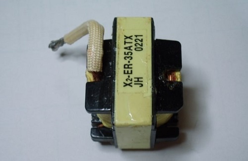
DC DC Converter 200W 2X30V SG3524 SG3525 Using EI33 Transformer In amplifier ICs, it can be used to run 100w…200w amplifiers, which operate symmetrically +-30v, with 12…14 volts. Since many amplifier circuits, especially suitable for use in cars, operate with symmetrical supply voltage, it is necessary to convert the 12v battery voltage and make it suitable for the amplifier. The transformer used is the output power transformer EI33, ER35 etc. found in PC power supplies. (In the past, EI33 was written on the transformers in the P3 times, but later different codes were used. They are no different from the EI33 core.) In the DC DC Converter circuit, we use the ATX Transformer in reverse. Normally, we get the output from the "primary" high voltage driven part of the transformer, and we drive the "secondary" low voltage output with MOSFETs. Original state of ATX Transformer, Transformer stands for
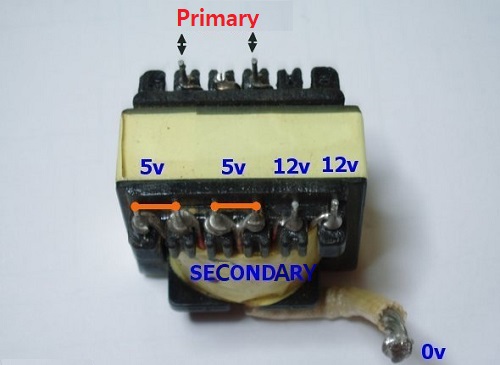
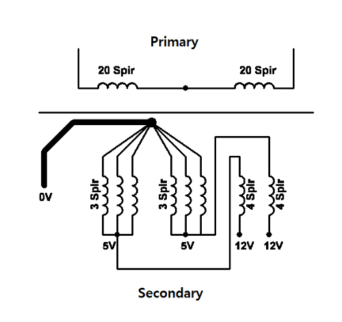
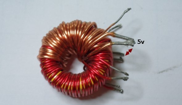
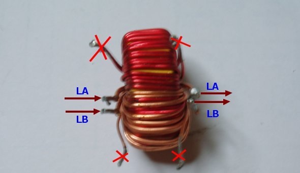
The 5v terminals seen in the picture are not used, the remaining windings are used. The simple diagram below explains the situation better.
There is also a REM remote section in the DC DC converter circuit, which is found in car amplifiers. Since this system is mostly used in car amplifiers, it can be canceled as required to stop the operation of the amplifier when the ignition is turned off, or this part can be combined with the +12v line to ensure continuous operation. The filter coil used in the DC output section is also in the ATX power supply. We separate the windings on the 5v output and use them on the +30v and -30v lines.
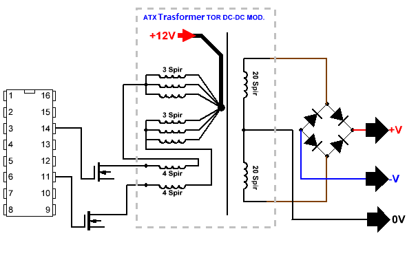
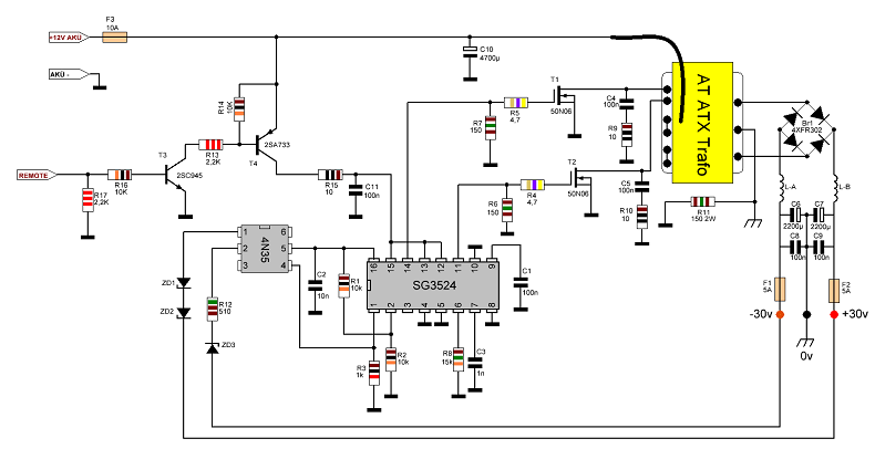
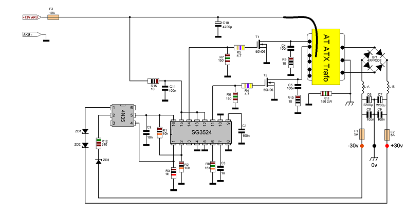
Circuit diagrams (+remote section removed)
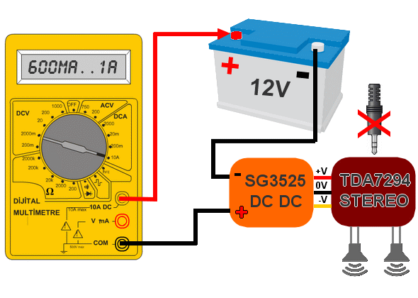
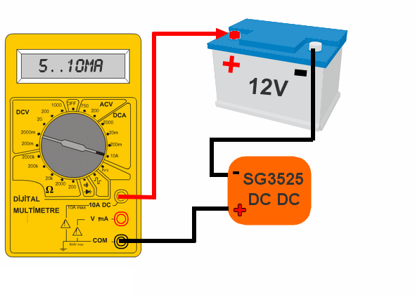
In addition, I am giving the information about the current draw, it will be useful for those who will do it, but I guess the current drawn varies depending on the integrated circuit, although it is the same, it is always different. I had 4 modules, all of them drew different current, that's why I said between 600ma….1a.
Finally; DCDC converter applications do not interest me much. I have never had such a long-term effort before. High voltage SMPS interests me more, but it was very useful in this study. First of all, if you are going to deal with DCDC converters, you need a very high power source for the experiments, because very high current is drawn during switching, sometimes you cannot even notice it. If there is not enough power, the MOSFETs burn out or other problems occur. This time, you may get bored while trying to find a fault in the circuit and buy a MOSFET at the cost... Circuit taken and studied from the 320volt.com website, for more details please do not hesitate to contact us |

+(39) 347 051 5328
Italy - Kazakhstan


09.00am to 18.00pm
About
We offer the best and economical solutions, backed by 27+ years of experience and international standards knowledge, echnological changes, and industrial systems.
Our Services
Marketing Materials


Marketing Materials1


