
|
0-30V 10A Adjustable Power Supply Circuit (LM723 TIP35) For your laboratory, here is a superpower supply designed around the evergreen LM723, capable of delivering an output voltage between 0 and 30 V with a maximum current of 10 Amperes. Protected against short circuits and complete with trip current threshold adjustment between 50 mA and 10 A. 20,000 microfarads of filtering capacitors, automatic switching of the input voltage from the transformer and warning light for the presence of radio frequency on the power supply line! Thanks to the bypass circuit, the power loss on the transistors is reduced. See; Bypass circuit with relay for regulated power supplies There are no files of the volt ampere meter circuit used in the regulated power supply circuit, but you can use different indicator circuits because it has no connection with the control of the main power circuit, it only makes measurements. High power circuit tests, battery charging etc. A quality power supply circuit that you can use in your workshop for.
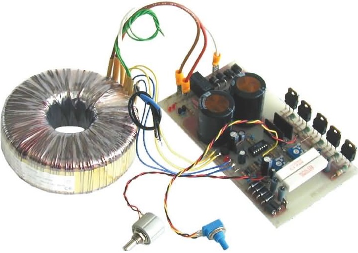
Figure 1 - TF1 transformer
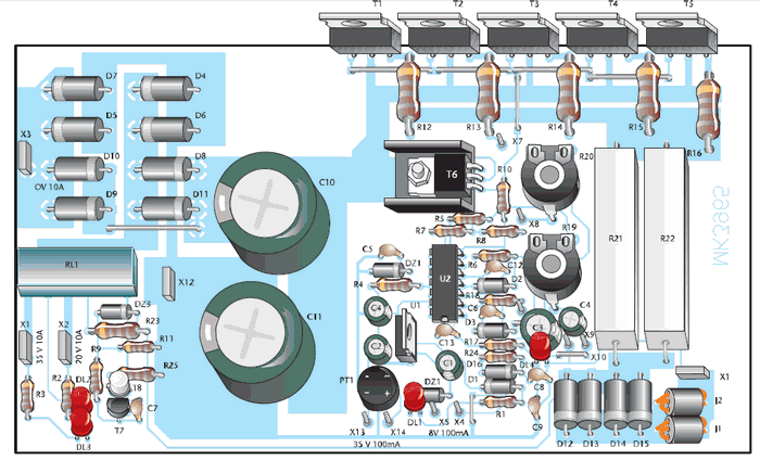
Figure 2 - Front circuit of the components
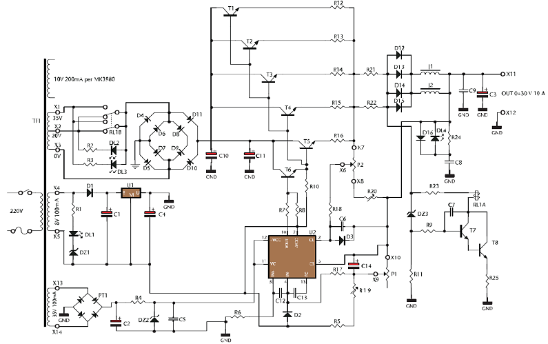
30V 10A Power supply circuit diagram
Figure 3 - Circuit diagram The electrical diagram of the MK 3965 power supply is depicted in the figure 3, we note that the TF1 transformer is equipped with 4 completely separate secondary windings: the first represents the power secondary, which supplies a voltage of 35 V with a 20 V tap and delivers a current of 10 amps; the second provides a voltage of 8 V 100 mA; the third a voltage of 35 V 100 mA; the fourth a voltage of 10 V 200 mA to power the MK3980 digital ammeter voltmeter. The voltage of the first winding is applied via the contacts of the relay RL1 to the rectifier diode bridge D4÷D11. As can be seen for each branch of the bridge two diodes have been placed in parallel to increase dissipation and switching speed. The voltage is then filtered by electrolytic capacitors C10 and C11 for a total of 20,000 μF; this voltage is then applied to the parallel of by-pass transistors T1÷T5. The voltage of the second winding is rectified by the diode D1, filtered by C1 and stabilized by the integrated circuit U1, which the output is connected to the negative of the circuit. This is to obtain a negative voltage with respect to the general ground, which applied to the U2 integrated circuit allows it to drop below the minimum voltage level (2V) obtainable from the 723. In this way, it is possible to achieve zero-volt output, so that even those circuits that require supply voltages of 1-1.2-1.5 V can be powered. The voltage of the third winding is straightened by the PT1 bridge, stabilized by the DZ2 zener diode, and then sent to the input of U2. The output voltage is regulated by means of the P1 multiturn potentiometer, the R19 trimmer, placed in series with it, determines the maximum voltage to be obtained at the output. The T7 and T8 transistors, the DZ3 zener diode and the associated components determine the tripping threshold and the drive of the RL1 relay coil. PRACTICAL EXECUTION AND CALIBRATION Now let's move on to the description of the assembly phases. Very care must be taken during the entire assembly phase to avoid unpleasant surprises when supplying food. You start by assembling the lower profile components and it follows gradually up to the larger ones, namely the RL1 relay and capacitors C10 and C11. To mount the D4÷D15 power diodes, fold the terminals with a pair of small pliers, but do not force too hard to avoid breakage. Continue by mounting the 5 power transistors, which must be soldered keeping their body at a height of about 10 mm from the printed circuit, before performing the final welding, check that the fixing holes of the fins coincide with the threaded holes present on the heatsink of the 3965/C container, (3965/C is supplied on request). The DL4 LEDs (! RF), DL2 (Sec 1), For connections, we recommend using cables with the following cross-sections: 1.5–2.5 mm2 for output connections 0.35mm2 for all other connections.
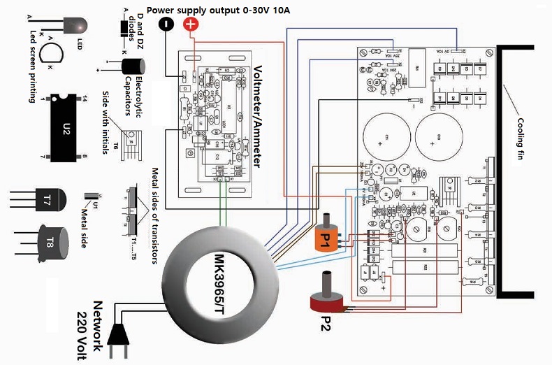
Figure 4 - Wiring of the power supply
The power supply can also be supplied with digital control via the PIC18 microcontroller. For more details do not hesitate to contact us. For the PDF which include also the PCB click here |
||||||||||||

+(39) 347 051 5328
Italy - Kazakhstan


09.00am to 18.00pm
About
We offer the best and economical solutions, backed by 27+ years of experience and international standards knowledge, echnological changes, and industrial systems.
Our Services
Marketing Materials


Marketing Materials1


