
|
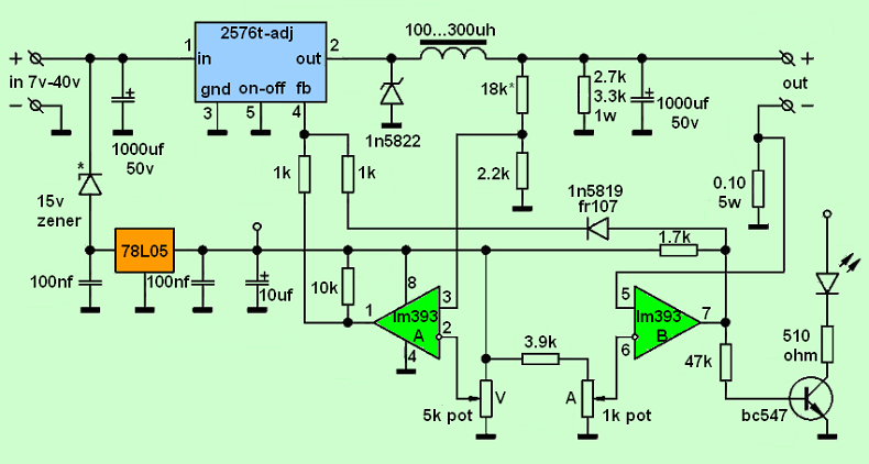
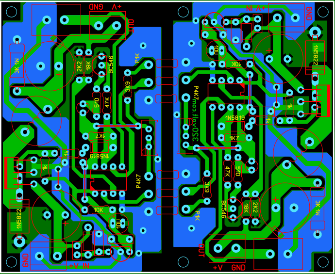
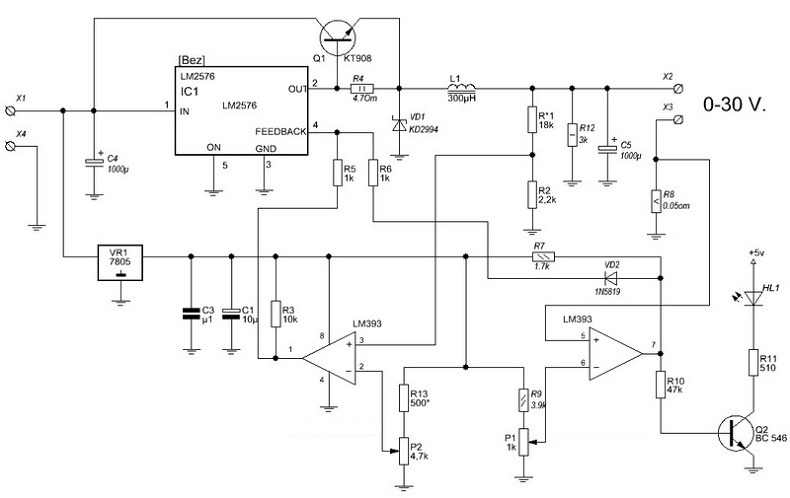
LM2576T-ADJ 0-30V 0-3A DC DC Adjustable Power Supply Circuit The voltage range of the power supply circuit, which is based on the LM2576T-ADJ adjustable switching regulator integrated, has an output current of 0-30V and 0.3A, although the output voltage varies depending on the input, it is customary to be 0-30V… It is indicated by the LED that the output current is limited, the input voltage is 7V…40V DC. There are not many external elements used in the circuit and it is not very complex. On the LM2576 power supply circuit, the LM393 comparator works with 5V and the 78L05 integrated circuit is used for regulation. If the input voltage is above 25V, a 15V zener must be connected to the 78L05 input. I added a jumper for this. If you are going to use it with 24V, just short circuit the jumper without using the zener. If you apply a higher input voltage, you must use 15V…18V Zener. You can apply the input voltage (7V-60V) above 40V using LM2576HV. Adjustment can be made up to 55 Volts. The power of the coil used for DC DC Adjustable power supply may be 4A or more. There are different opinions about its value. I applied with 100uh, but according to the LM2576 datasheet, there are those who say that 150uh and 300uh should be used. Tests can be made regarding the coil value depending on usage. The cooler I used was a bit small, you may need to use a larger cooler, although it varies depending on the power consumed or the use of the fan. The 1N5822 diode seen in the diagram is at the full limit value of 3 amps, I used a 4 amp diode, in addition, a 5 amp SMD fast diode was added in the PCB drawing DC DC Adjustable power supply PCB dimensions: 76.5mm 46mm In the PCB drawing, I made the GND and input-output lines double-layered to strengthen them. Optionally, one-sided printout can be made and used without pressing the C1 upper layer. Only LM393 pin number 4 should be connected to the chassis. I forgot to add a jumper to it.
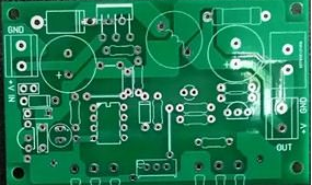
Figure below shows the PCB circuit
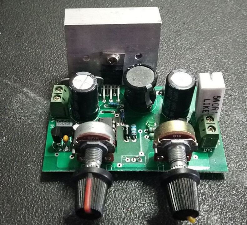
I couldn't do long term tests because I was busy, but there are many people who made it, I tested it, it turned out to be a working circuit, even those who sell it in kit form, you can also draw more power ( 0.5A, 0-10A) adding BJT transistor (2SC4468, 2SD718 maximum voltage R1) diode VD1 SFA1604G 16A 200V Caution: Do not short circuit. the input, LM2576 goes directly, the LM2576 can broken easly. Circuit Diagram
For control via the push button without using potentiometers, is available the display controlled by a PIC18Fj. The PIC controls the output voltage and current thanks to 4 ADC converters. In the case of short circuits, the PIC disables all functions in real-time. To reset the power supply, it is required to turn it off and on again. The case and PCB main board, including all components, are available on the website. For more details see Figure below
For further information about this power supply, do not hesitate to contact us.
|

+(39) 347 051 5328
Italy - Kazakhstan


09.00am to 18.00pm
About
We offer the best and economical solutions, backed by 27+ years of experience and international standards knowledge, echnological changes, and industrial systems.
Our Services
Marketing Materials


Marketing Materials1


