
|
PIC16F877P Adjustable digital power supply with LCD display Adjustable microcontroller-controlled digital power supply project with all its details, volt and ampere values can be read on the LCD, PCB box design, 3D views, source software prepared in ASM language. Feature
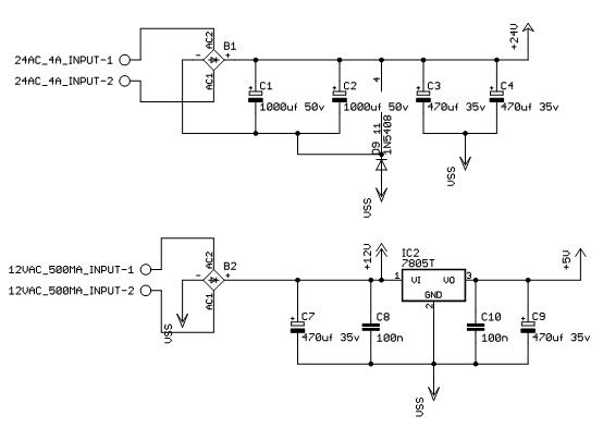
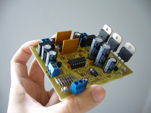
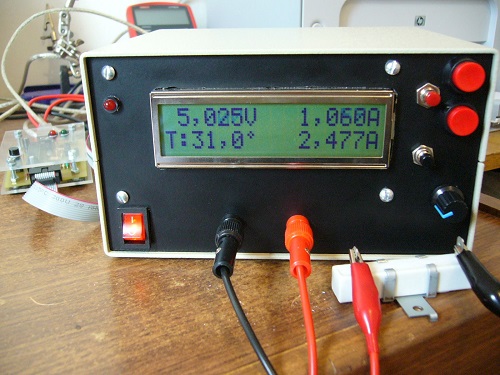
A power supply is one of the most used tools in an electronics laboratory, on the market there are various voltages (12v, -12v, 5V, -5V) with high amperages. The idea of this power supply is that it is an analog supply controlled/regulated by a microcontroller, easy to assemble, cheap and has multiple features with expansion possibilities. Forced ventilation must be controlled by temperature and consumption, as design constraints for 25V at 3 or 4A may compromise some components. External power lines should be isolated from the control section, this reduces possible voltage drops due to ventilation, LCD backlight or use of other devices. In general the weight of two transformers plus the electronics can lead to the source having a significant weight (3kg in my case), so a 3mm aluminum cabinet will be used. The circuit consists of two parts, one of which is stepper transistor analog, LM324N in operation, transformers, 7805 regulator, control inputs and outputs. The control part consists of the microcontroller, LCD, buzzer, ICSP connector, and connectors to the input buttons and encoder if selected for use. The regulator circuit is dominated by the LM324N component; this is a quadruple process that gives us a maximum voltage of 32V and the possibility of using low tolerance resistors (1% is recommended). I divided the circuit into sections to understand and analyze it better
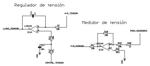
Power Stage Power stage In this source the control stage (digital part) is the most elaborate, while the analog part is the classic part with the addition of control against short circuits provided by T1,T2. 0.51ohm resistors grounding the base of power transistors T3 (BC547) and Q1..3. Voltage regulation The operation will be as follows, the constant current source formed by D4, D5, R5, Q4 and R1 provides 2mA to the base of the darlingtons. The reference of said transistors is controlled by the operational ones of the control part.
This is done with the voltage divider formed by R13, R14 and R17 but if there is 25v it will be 25.25v as the reading is affected by the current supplied and drops across the resistor Rs (shunt resistor, 10 1ohm resistors in parallel) when at the output so IC1D which is the inverting amplifier is used, For example, if there is a consumption of 2.5A, a drop of 0.25V appears at the ends of Rs. IC1D is then used to perform said correction, so we will see that it has the formula: Vo = -(R18/(R19+R20)) * Vin then if Vin is 0.25V as we said Vo = -( 10k/40k )*0.25 Vo = -0.0625V (remember this number)
OK, the potential between 25.25v and the reference -0.0625v gives us the value 25.3125v, then at the output of the resistive divider formed by R13, R14 and R17 there is:
Vo = Vi * (R17 / (R17 + R13 + R14) = 5,0625v
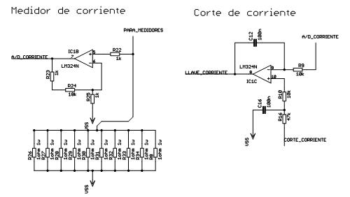
and since the ground reference of the LM324 amplifier is -0.0625 thanks to D9. Voltage remains at 5V ready to input into comparator IC1A (takes) Vo = Vs+, when V1 > V2 Since Vo = Vs-, V1 < V2, compares the output of the divider voltage with the selected voltage. In this way it regulates the output voltage (or cuts off if the voltage exceeds the desired value). The same goes for current, if we follow the suggested example, if there is a consumption of 2.5A, there will be 0.25vy at the non-inverting operational input since Vo = (1+ 19k/1k) * 0.25 = 5V. And the output ends up at the inverter input of IC1C and the same thing happens as in IC1A, that is, the reference of the transistors is regulated or cut off if the pre-selected maximum is exceeded. Analysis of the encoder Encoder for continuous rotation with three output pins. Two gray code output channels (http://es.wikipedia.org/wiki/Gray_Code). It creates three binary sequences for each spin: 11,10, 00, 01. Two-bit Gray code 00 01 11 10 The encoder has three terminals; one is the common terminal and the others are digital outputs generated by the internal contacts of the device. Creates the following sequence Channel EU Status1 0 0
The same is with the current, following the proposed example, if there is a consumption of 2.5A, we would have 0.25v at the input of the non-inverting operational and since Encoder analysis Encoder for continuous rotation with three output pins. Two gray code output channels (http://es.wikipedia.org/wiki/Gray_Code). Generates three binary sequences 11,10, 00, 01 for each spin. Two-bit gray code
The encoder has three terminals, one is the common terminal, and the others are the digital outputs generated by the internal contacts of the device. Generate the following sequence
Clockwise rotation -> 00 01 11 10 00 <- counterclockwise="" in="" n="" rotation="" direction="" span="" style="font-weight: bold;">Connection to the PIC The source code below shows the sequence ; * * * * * * Then the interrupt service should be: ; Interrupt Service Routine Pre-amble, save state, As you can see, the TMR0 interrupt is reloaded first to ensure a tick rate (and this is also the first verified interrupt!) Then the state of the encoder is checked in the call to QUAD_STATE: ; RLF Q_NOW,F ; Rotate Q_NOW Left Figure below shows the circuit how should be
For more details regarding components, circuit Diagram, and PCB plate, do not hesitate to contact us. Also available the simulator and new modification with PIC24. The program for the PIC16F877 is all written in Assembly. |

+(39) 347 051 5328
Italy - Kazakhstan


09.00am to 18.00pm
About
We offer the best and economical solutions, backed by 27+ years of experience and international standards knowledge, echnological changes, and industrial systems.
Our Services
Marketing Materials


Marketing Materials1


