
|
Li-ion Battery Charger - MCP73831 and TP4056
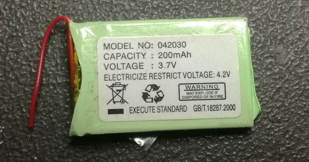
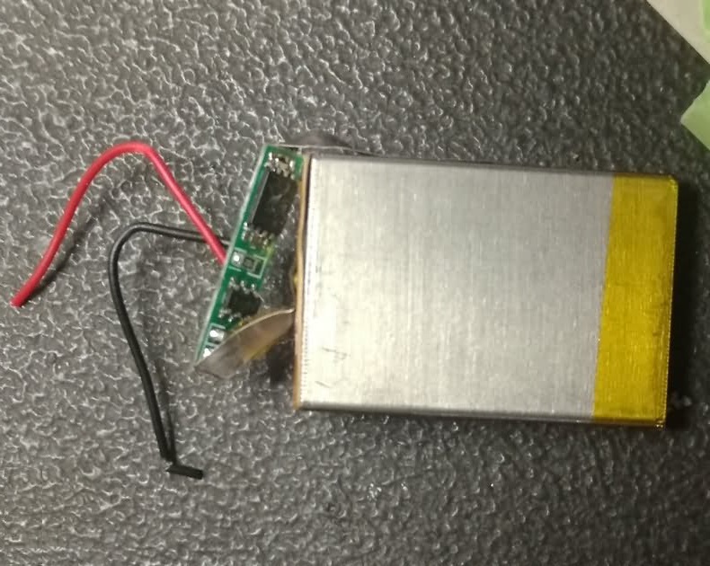
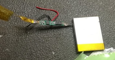
Li-ion and Li-po batteries are highly usable power sources that are very suitable for many projects with their size and power… but the charging process is sensitive and they must be used with additional protection circuits. If these batteries are charged or discharged incorrectly, they can easily catch fire cause serious damage. This type of battery can be of different shapes, which is why it is widely used in mobile phones, flashlights, power banks, and even on electric cars, thanks to the charging speed. You may have seen a small circuit board inside slim-type lithium batteries. These circuits are the over-discharge protection of the battery. In case of any malfunction or not charging for a long time, when the voltage of the battery drops to around 2.5v…2.7v, it separates the minus line between it and the load it is connected to. MP3 players, tablet computers, mobile phones, etc. Slim-type lion batteries in many devices generally have an additional discharge protection circuit.
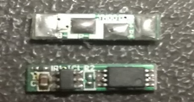
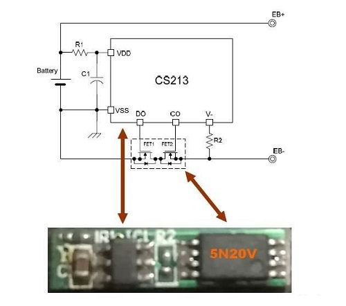
Battery Protection Circuit Diagram
The most commonly used MOSFET in low-power applications is 5V20V. It has a very low gate voltage (2.7V) and 5 ampere power suitable for use in 3.7V lion batteries. In some applications, higher currents can be controlled by connecting more than one 5N20V MOSFET in parallel to the CS213 control integrated. 5N20V CS213 Module Used
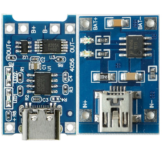
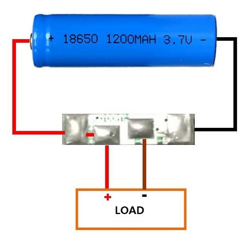
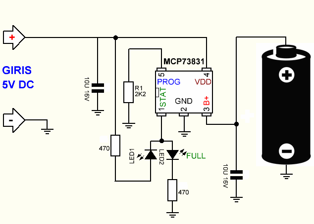
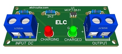
Finally, an important detail is that after connecting the battery protection module to the battery, the module may not output output. I have seen this situation in many battery protection modules I have tested, it is necessary to provide charging voltage for it to output, then it works normally. After clarifying the protection module, let's move on to the battery charger MCP73831 Li-ion Battery Charger Circuit Diagram
The MCP73831 device is an advanced linear charge management controller for use in space-limited, cost-sensitive applications. The MCP73831 device limits the charge current based on die temperature during high power or high ambient conditions. The Circuit The circuit is very simple and uses few external components which facilitate the assembly and reduce the assembly cost, the standard charging voltage regulation is normally set at 4.2V.
The constant current charging value is adjusted through resistor 2.2K ohms R3, which in our circuit is programmed for a ~450mA charge. Using a simple formula, we can vary this constant charging current:
Formula:
Remember that the minimum charging current for this device is 15mA and the maximum current is 500mA. Features
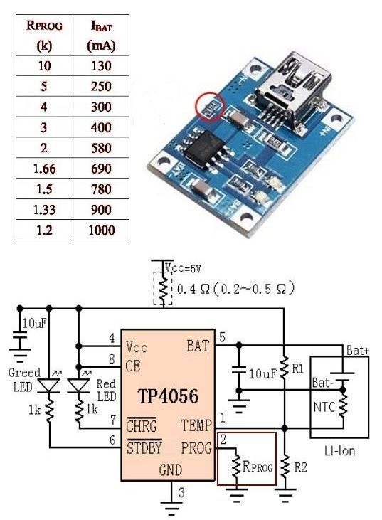
The MCP73831 circuit is provided by Microchip here the datasheet The PCB - Printed Circuit Board We are offering the PCB, in GERBER, PDF and PNG files, for you who want to do the most optimized assembly, either at home. TP4056 Connection
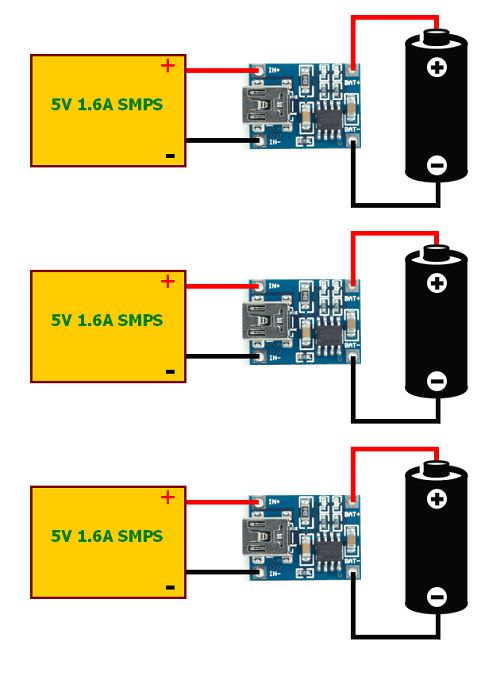
The current of the TP4056 charging IC can be adjusted. TP4056 modules generally have a “Prog” resistor installed according to the highest output current. By changing the resistor connected to pin 2 of TP4056, the current can be adjusted between 130ma….1000ma.
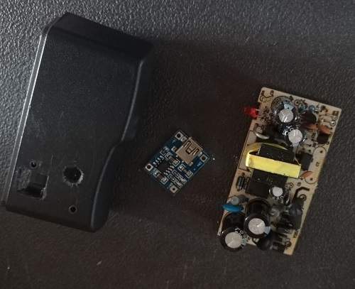
Regarding the SMPS module, I suggest using any power supply from a laptop that is no longer used but still works, for more details see the figure below.
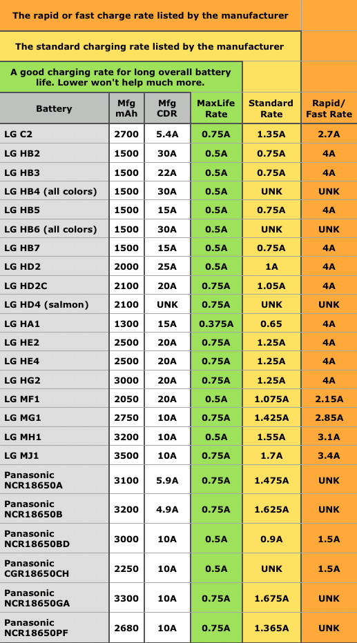
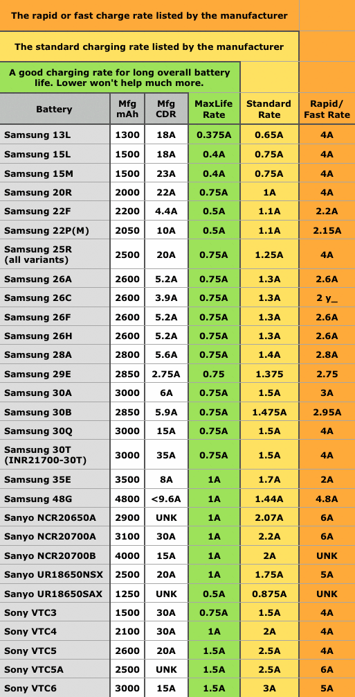
What Should the Battery Charging Current Be? Please note that you will be able to read the information on the tablet from LG, SONY, PANASONIC, SANYO, SAMSUNG.
The green zone is the charging current suitable for long battery life. It varies depending on the battery brand and model. There are values between 0.3…..1.5a. Battery Charge from solar Panel
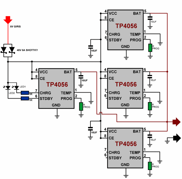
It is possible to install modules in parallel as per the figure above and get a higher amperage. The PROG current adjustment resistor of all integrated circuits is installed at 1.5K. In the current resistance table, it appears as 1.5K and 780mA. A total of 3.1A charging current is obtained. In a parallel connection, the indicator LEDs of only one integrated circuit are connected, the LED connection legs of the other integrated circuits are left empty, 2 SS54 shock diodes are connected in parallel to the + plus input of the integrated circuits, its power is 5A and its voltage is 40V, for more details see figure below TP4056 4X Parallel Connection Diagram
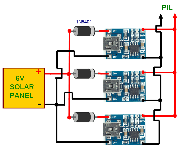
If you are going to use a complete module, you can use it by connecting a diode with the appropriate current to the + plus input of each module, as in the 6V solar panel connection above. The input voltage of the TP4056 integrated circuit is the lowest 4V, the highest 8V, ideally 5V. In the diagram above, there will be very little voltage loss in the parallel connected shock diodes if parallel. If your input voltage is 5V in the connection, it would be better to use a shock diode. 0.7V loss above 6V does not cause any problems, but there may be a problem with 5V input voltage because there will be losses in the integrated circuit. Warnings: never leave a live lithium battery under charge in closed rooms, it could explode and fire. Never, do any experiments for lithium batteries if you are not sure. |

+(39) 347 051 5328
Italy - Kazakhstan


09.00am to 18.00pm
About
We offer the best and economical solutions, backed by 27+ years of experience and international standards knowledge, echnological changes, and industrial systems.
Our Services
Marketing Materials


Marketing Materials1


