
|
Working Principle of an Relay The element that controls one or more groups of switches (opens or closes the switches) in order to operate (switch) a receiver (load) operacccccc The coils of relays, which are generally fed with voltage between 5V-48V, draw current between 5mA-150mA. Its contacts can withstand current values between 0.5A-70A. A wide coil supply voltage range provides convenience in application circuits. In this way, it is possible to drive it with both logic and analog circuits. When controlling high-current circuits, the heating that may be caused by the current passing through the contacts requires the use of contactors instead of relays in these circuits.
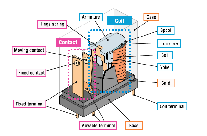
Figure 1 -Standard relay philosophy
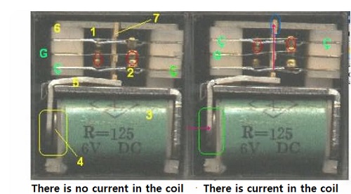
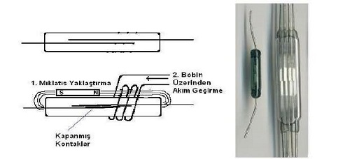
Magnetic Relays The current passing through a conductive wire covered with an insulating surface wrapped around an iron rod creates a magnetic field and attracts nearby metals towards itself. Magnetic relays are manufactured by taking advantage of this feature of the current. Figure 2 - inside magnetic relay Magnetic relays consist of three basic parts. These are relay coil, relay contacts and pallet. The coil consists of a large number of conductive wires wrapped in a plastic sheath placed on an iron core (shown as 4) manufactured in the shape of a cylindrical or rectangular prism (shown as 3). The pallet (shown as 5) is a piece of soft iron that moves by being affected by the magnetic field of the coil. The reason why soft iron was chosen as the core is that it easily gains a magnetic field and at the same time loses this feature easily. At the point where the pallet contacts the contacts, there is an insulating material called fiber (shown as 7). When there is no magnetic field, it is held in tension by a spring. Contacts (shown as 1 and 2) are good conductive materials that allow current to flow when they come into contact with each other. Apart from these, a relay also has an insulating ground material (shown as 6) that prevents unintentional contact of the contacts. Language Contact Roles The relay made by placing metal contacts that are easily affected by the magnetic field inside an air-emptied glass tube is called tongue contact, and if the number of contacts is large, it is called tongue contact relay. Reed contacts have many uses such as liquid level control, underwater devices, remote control switches and warning lights of automobiles. In relays with tongue contacts, it is sufficient to approach a magnet or pass current through the coil wound on the glass sheath to close the contact. Tongue contacts are magnetic field controlled switches. The opening and closing of the switch depends on the change in the magnetic field.
Figure 3 - Relay Contact Deals
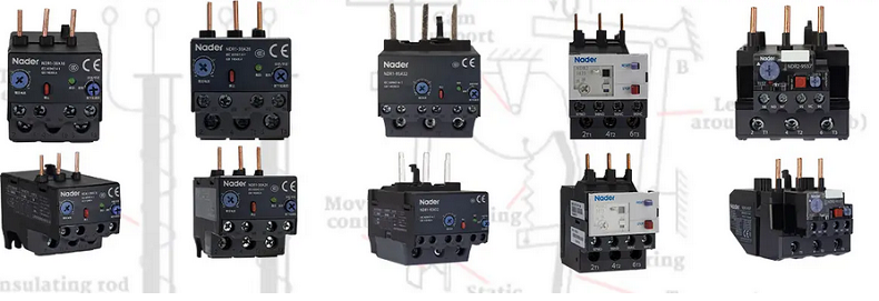
Thermal Relays It is a type of relay that opens or closes its contacts according to the temperature change in the environment. Thermal relays are frequently used to stop motors that overheat during operation or to prevent further heating at the appropriate temperature level in heat-producing devices such as irons and hair dryers.
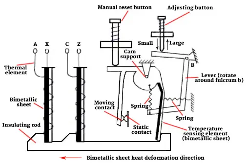
Figure 4 - Structure of thermal relay Working principle of thermal relay When the motor operates normally, the thermal element of the thermal relay will not generate enough heat to make the protection function act, and its normally closed contact will keep closed state; when the motor is overloaded, the thermal element of the thermal relay will generate enough heat to make the protection function act, and its normally closed contact will be disconnected to make the motor lose power through the control circuit, so as to protect the motor. After troubleshooting, the thermal relay should be reset before the motor can be restarted.
Figure 5 - Thermal Relay
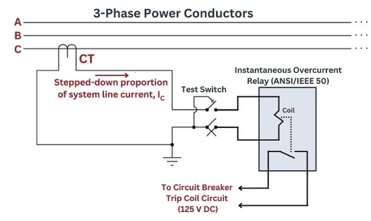
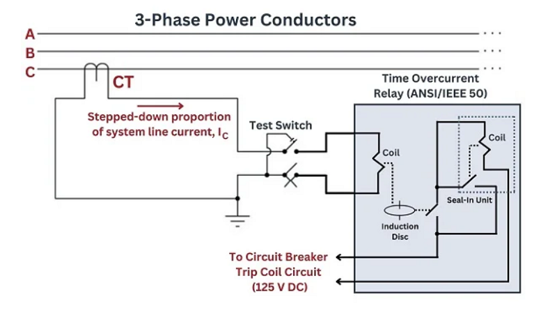
Overcurrent Protection Relays Fuses placed at the beginning of the line in a load circuit protect the line, not the load, due to their operating characteristics. Various relays are used to protect the loads before failure. The overcurrent relay is used to prevent damage caused by overcurrents to the motor windings. Overcurrent protection relays are designed to protect motors and systems against overcurrent. Electromechanical 50 (instantaneous overcurrent) relays are models of simplicity, consisting of nothing more than a coil, armature, and contact assembly (a “relay” in the general electrical/electronic sense of the word). Spring tension holds the trip contacts open, but if the magnetic field developed by the CT secondary current becomes strong enough to overcome the spring’s tension, the contacts close, commanding the circuit breaker to trip:
Figure 6 - Relay Overcurrent Diagram The protective relay circuit in the above diagram is for one phase of the three-phase power system only. In practice, three different protective relay circuits (three CTs, and three 50 relays with their trip contacts wired in parallel) would be connected together to the circuit breaker’s trip coil, so that the breaker will trip if any of the 50 relays detect an instantaneous overcurrent condition. The monitoring of all three line currents is necessary because power line faults are usually unbalanced: one line will see a much greater share of the fault current than the other lines. A single 50 relay sensing current on a single line would not provide adequate instantaneous overcurrent protection for all three lines.
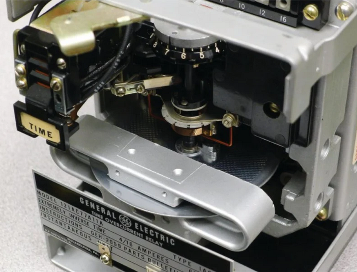
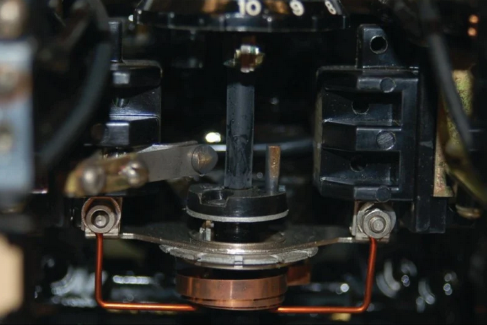
Figure 7 - Relay Overcurrent The round disk you see in the photograph receives a torque from an electromagnet coil assembly acting like the stator coils of an induction motor: alternating current passing through these coils cause alternating magnetic fields to develop through the rear section of the disk, inducing currents in the aluminum disk, generating a “motor” torque on the disk to rotate it clockwise (as seen from the vantage point of the camera in the above photo). A spiral spring applies a counter-clockwise restraining torque to the disk’s shaft. The pickup value for the induction disk (i.e. the minimum amount of CT current necessary to overcome the spring’s torque and begin to rotate the disk) is established by the spring tension and the stator coil field strength. If the CT current exceeds the pickup value for a long enough time, the disk rotates until it closes a normally-open contact to send 125 VDC power to the circuit breaker’s trip coil.
Figure 8 - Relay Overcurrent
Figure 9 - Relay Overcurrent
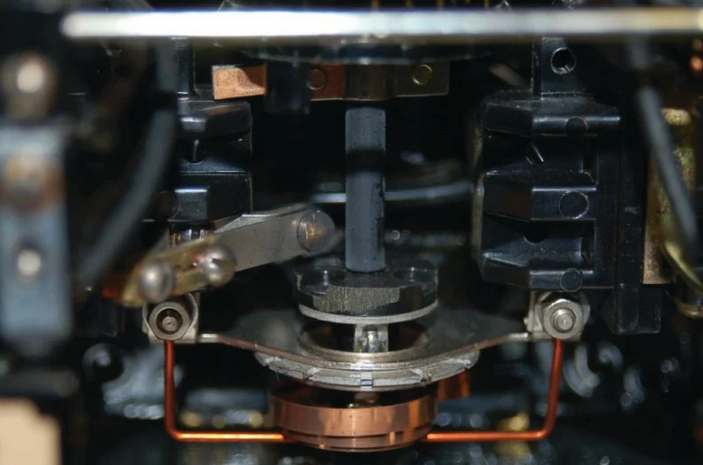
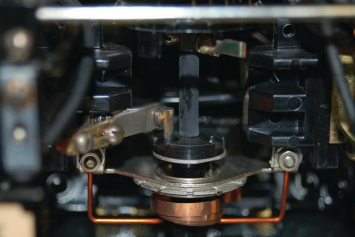
Figure10- Relay Overcurrent The mechanical force actuating the time-overcurrent contact is not nearly as strong as the force actuating the instantaneous overcurrent contact. The peg may only lightly touch the stationary contact when it reaches its final position, failing to provide a secure and lasting electrical contact when needed. For this reason, a seal-in relay actuated by current in the 125 VDC trip circuit is provided to maintain firm electrical contact closure in parallel with the rotating peg contact. This “seal-in” contact ensures a reliable circuit breaker trip even if the peg momentarily brushes or bounces against the stationary contact. The parallel seal-in contact also helps reduce arcing at the peg’s contact by carrying most of the trip coil current.
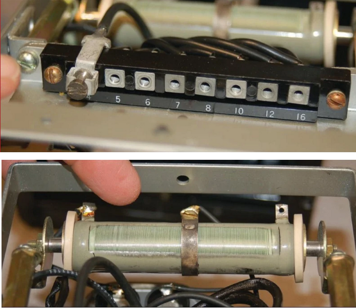
Figure11- Relay Overcurrent Diagram The seal-in unit is shown as an electromechanical relay connected with its contact in parallel with the induction disk contact, but with its actuating coil connected in series to sense the current in the 125 VDC trip circuit. Once the induction disk contact closes to initiate current in the DC trip circuit, even momentarily, the seal-in coil will energize which closes the seal-in contact and ensures the continuation of DC trip current to the circuit breaker’s trip coil. The relay’s seal-in function will subsequently maintain the trip command until some external contact opens to break the trip circuit, usually an auxiliary contact within the circuit breaker itself. Calibrating Overcurrent Devices Calibration of a time overcurrent (51) relay consists first of verifying that the unit “picks up” (begins to time) if ever the current magnitude exceeds the prescribed pickup value. In electromagnetic relays such as the General Electric model showcased here, this setting may be coarsely adjusted by connecting a movable wire to one of several taps on a transformer coil inside the relay, varying the ratio of CT current sent to the induction disk stator coils. Each tap is labeled with the number of whole amperes (AC) delivered by the secondary winding of the CT required for relay pick-up (e.g. a tap value of “5” means that approximately 5 amps of CT secondary current is required for induction disk pickup). A fine adjustment is provided in the form of a variable resistor in series with the stator coils.
Figure12- Relay Overcurrent Calibration Proper setting of the pickup tap value is determined by the maximum continuous current rating of the system being protected and the ratio of the current transformer (CT) used to sense that current.
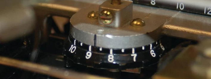
Figure13- Relay Overcurrent Calibration The amount of disk rotation necessary to close the trip contact may be set by adjusting the position of this time dial: a low number on the time dial (e.g. 1) means the disk need only rotate a small amount to close the contact; a high number on the time dial (e.g. 10) sets the resting position farther away from contact, so that the disk must rotate farther to trip. These time dial values are linear multipliers: a time dial setting of 10, for example, exhibits twice the time to trip than a setting of 5, for any given overload condition. Time Overcurrent Relay Curves Time overcurrent relays exhibit different “curves” relating trip time to multiples of pickup current. All 51 relays are inverse in that the amount of time to trip varies inversely with overcurrent magnitude: the greater the sensed current, the less time to trip. However, the function of trip time versus overcurrent magnitude is a curve, and several different curve shapes are available for United States applications:
Time curves standardized by the Swiss standards agency IEC (International Electrotechnical Commission) include:
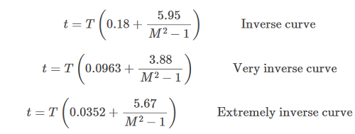
The purpose for having different curves in time-overcurrent relays is related to a concept called coordination, where the 51 relay is just one of multiple overcurrent protection devices in a power system. Other overcurrent protection devices include fuses and additional 51 relays at different locations along the same line. Ideally, only the device closest to the fault will trip, allowing power to be maintained at all “upstream” locations. This means we want overcurrent protection devices at the remote end(s) of a power system to be more sensitive and to trip faster than devices closer to the source, where a trip would mean an interruption of power to a greater number of loads. The trip time formulae programmed within a Schweitzer Engineering Laboratories model SEL-551 overcurrent relay for inverse, very inverse, and extremely inverse time functions are given here:
Where, Multiples of pickup current (e.g. if Ipickup= 4.5 amps, a 9.0 amp signal would be M=2) REVIEW
|

+(39) 347 051 5328
Italy - Kazakhstan


09.00am to 18.00pm
About
We offer the best and economical solutions, backed by 27+ years of experience and international standards knowledge, echnological changes, and industrial systems.
Our Services
Marketing Materials


Marketing Materials1


