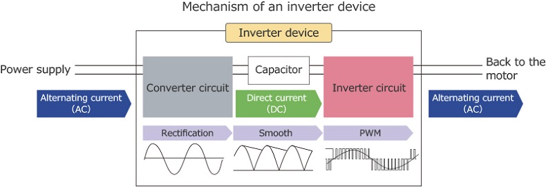
Power Inverter Working Principle

Introduction

 The inverter is a device that converts DC electricity (battery, storage battery) into AC power with a fixed frequency and voltage or with frequency modulation and voltage management (usually 220V, 50Hz sine wave). It is made up of semiconductor power devices as well as drive and control circuits for inverters, The creation of new high-power semiconductor devices and drive control circuits has been aided by the advancement of microelectronic and power electronics technologies. Insulating gates are now often used in inverters, Polar transistors, power field-effect transistors, MOSFET, MOS controller thyristors, and intelligent power modules are examples of advanced and easy-to-control high-power technologies. The control circuit has also evolved from an analog integrated circuit to being controlled by a single-chip microprocessor or a digital signal processor, allowing the inverter to progress in the direction of systematization, full control, energy efficiency, and multi-function. Air conditioners, home theaters, electric grinding wheels, electric tools, sewing machines, DVDs, VCDs, laptops, TVs, washing machines, range hoods, refrigerators, video recorders, massagers, fans, lighting, and other electronic devices use it.

Working Prnciple of Power Inverter

We'll start the introduction by explaining the inverter device's mechanism in detail. The inverter device's role is to control the voltage and frequency of the power supply and seamlessly change the rotation speed of motors used in home appliances and industrial machineries.
The first thing to keep in mind when it comes to enriching your understanding of the internal structure of an inverter device, is that the converter circuit converts alternating current (AC) coming from the power source into direct current (DC), and the inverter circuit changes the converted direct current (DC) back into alternating current (AC). They work as a set. The diagram below shows the role they both play and the way they work.

Inverter12

Figure 1  - Power Inverter Circuit Diagram

Normally, to reduce or increase the speed of a motor in AC, inverters reduce or increase the frequency of the voltage via the MOSFETs and the control circuit (microelectronic). This is the classic operation of an inverter on a THREE-PHASE or single-phase motor. Let's take the spin cycle of a washing machine as an example. The MOSFETs increase or decrease the frequency of the voltage to increase or decrease the speed.

Firstly, the converter circuit used in the front part constantly converts alternating current to direct current. This process is called rectification. The wave’s direction and magnitude changes periodically over time since alternating current is a sine wave. Therefore a diode, which is a semiconductor device, is used so as to pass electricity in a forward direction to convert it into direct current, but not in the reverse direction.
When direct current goes through the diode, only the forward direction passes electricity and a positive peak appears. However, the other half of the cycle will be wasted because it does not pass the peak in the negative direction. The reason why the diode's structure is shaped like a bridge is so that it can pass the negative peak in a forward direction. This is called full-wave rectification due to the fact that it transforms both the forward and negative wave peaks.
However, full-wave rectification by itself cannot produce a smooth waveform as traces of the alternating current and rippled voltage fluctuations will remain. Therefore, in order to clean these up, the capacitor is repeatedly charged and discharged, gently smoothing and changing the waveform close to that of direct current.
The inverter circuit then outputs alternating current with varying voltage and frequency. The DC/AC conversion mechanism switches power transistors such as "IGBT (Insulated Gate Bipolar Transistor)" or the MOSFET (IRF) and changes the ON/OFF intervals to create pulse waves with different widths. It then combines them into a pseudo-sine wave. This is called “Pulse Width Modulation (PWM)”.
The computer controls the pulse width automatically. Some of the dedicated one-chip computers that control the motor include a product with the PWM function pre-installed. This makes it possible to create pseudo-sine waves of various frequencies and control the rotation speed of the motor simply by specifying desired parameters. For more details see Figure 2 Below

Inverter13

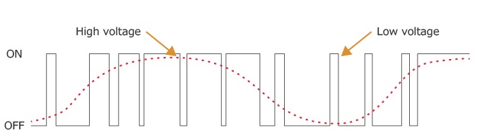
Figure 2  - Sine Wave and Pulse

Categorizing use cases of inverter devices and circuits by voltage and frequency

Inverter circuits and devices are used in various electrical products such as household air conditioners, refrigerators, IH (induction heating) cookers, fluorescent lights, computer power supplies (including UPS), industrial fans, pumps, elevators, and cranes. They are widely used and have become an integral part of our lives.

  • VVVF Voltage/frequency Industrial motors, pumps, air conditioners, refrigerators, etc.
  • CVVF Frequency only Electromagnetic cooker, rice cooker, fluorescent lights, etc.
  • CVCF Constant voltage and frequency Computer power supply, UPS (uninterruptible power supply), etc.

As mentioned in the beginning, inverter circuits and devices are used in household air conditioners, refrigerators, industrial pumps, elevators, etc. to adjust the motor's rotation speed. In this case, the inverter is used to change both voltage and frequency, this is called "VVVF (Variable Voltage Variable Frequency)".
There are no built-in motors in IH cookers or fluorescent lamps, but changing the frequency with the inverter circuit lets you finely adjust heat and brightness. For example, an IH cooker uses high frequency in its coil that heats the pot, utilizing the inverter circuit. Fluorescent lamps also use alternating current in high frequency to increase the lighting speed in order to maintain brightness and suppress flickering with low power consumption. At this time, the inverter circuit changes only the frequency, so it is called "CVVF (Constant Voltage Variable Frequency)".
Last but not least, the inverter circuit also works in computer power supply units. It may seem meaningless because it is used to output a constant AC voltage or frequency from a constant AC (or DC) voltage or frequency. However, it can be used as a stable power supply when the frequency of the AC commercial power supply fluctuates or a power failure occurs. Since it maintains a constant voltage and constant frequency, it is called "CVCF (Constant Voltage Constant Frequency)".

favicon bacd

+(39) 347 051 5328

Italy - Kazakhstan

09.00am to 18.00pm

About

We offer the best and economical solutions, backed by 27+ years of experience and international standards knowledge, echnological changes, and industrial systems.

Marketing Materials

Spring Renovation
Industry
US Gas Company
Construct
Plus Project
Vam Drilling Service
X Project
X Project
Cabrrus Training

Marketing Materials1

Spring Renovation
Industry
US Gas Company
Construct
Plus Project
Vam Drilling Service
ultrasonic sensor
ultrasonic sensor
Cabrrus Training