
|
Technique for using the Hot Air Rework Station, Soldering Heat Gun
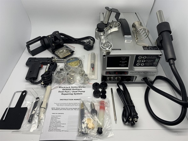
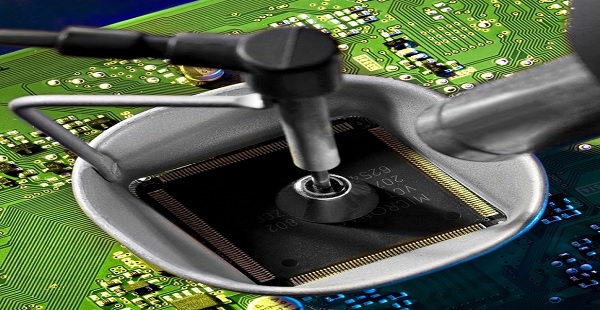
Figure 1 - BlackJack BK8000 Multipro Station Warning Working on this type of welding is not so easy, because the material to be remove or welded undergoes strong temperature stresses. For this reason, before using this station it is important to know the datasheet of the component that should be removed, and also the connection slopes on the PCB, and then act accordingly. Introduction Hot-air stations or heat guns are very useful tools and are essential for any electronics workshop. When working with or building printed circuit boards, especially micro SMD, is very easy to make errors. Whether you're relying on machines to do the building for you or building by hand, solder can often have a mind of its own. Sometimes the person doing the building (or the person programming the machine that does the building) can make a mistake. Quad Flat Pack Surface Mount Chip (removal) This procedure will guide those unfamiliar with QFP (Quad Flat Pack) chips and their design, summarising the removal process from start to finish. See Figure 2 below
Figure 2 - Surface Mount Chip Materials and Tools required This is everything required to install or remove a chip on a main board.
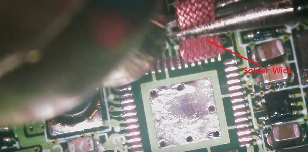
BlackJack BK8000 Multipro Station We use this station because, based on our work, it has proven to be very reliable. The BlackJack SolderWerks BK8000Multi-Pro Advanced Repair System is a digital multipurpose rework system equiped with a powerful dual port, dual pump design. This dual port, dual pump system allows seamless work flow as the hot air gun, soldering iron and de-soldering gun can be operated simultaneously. This design feature differs from many hot air rework systems that are designed to share the same pump requiring the de-soldering gun and the hot air gun to share the same port. With the BK8000Multi-Pro system, the entire rework process can be started and finished without any loss of time due to tool switching, wait times for tools to heat up to operating temperature or loss of functionality due to the limitations of lesser single pump designs. Even ambitious protoyping is a snap with the BK8000Multi-Pro. Wick Solder
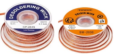
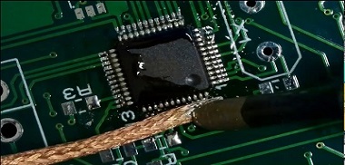
Wick, Solder Wick, Desoldering Wick, Solder Braid, Desoldering Braid. All of these names refer to the same thing. It is a method of removing unwanted solder using flux and braided copper wire. IC Chip Remover Tool Kit
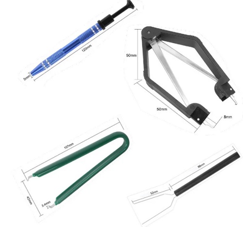
Figure 5- IC Chip Remover Tool Kit Introducing the 4 Pieces IC Chip Remover Tool, the ultimate solution for safely and easily extracting IC chips and keyboard switches. Whether you are a professional in the electronics industry or a DIY enthusiast, this tool set is a must-have for any disassembly project. Do you need to remove IC chips from electronic components? Look no further. Our IC chip remover tool is designed with precision and efficiency in mind. Equipped with a 4-claw prongs grabber, it allows you to securely grip and pull out IC chips without causing any damage. With this tool, you can confidently disassemble electronic devices without worrying about delicate components. The IC PLCC chip extraction tool included in this set is perfect for extracting PLCC chips. Designed specifically for PLCC chips, this tool ensures a secure grip and effortless extraction. It simplifies the process of removing PLCC chips, saving you time and effort. In addition to the IC chip remover and PLCC chip extraction tool, this set also includes a keyboard key switch test pencil tool. This tool allows you to easily test the functionality of keyboard switches. Simply touch the pencil to the key switch, and it will light up to indicate whether the switch is functioning properly. No more guessing or struggling to test keyboard switches. Made from high-quality materials, these tools are durable and built to last. They are also compact and lightweight, making them perfect for on-the-go use. Whether you are working on a professional project or tinkering with electronics at home, these tools will meet all your needs. Solder Flux
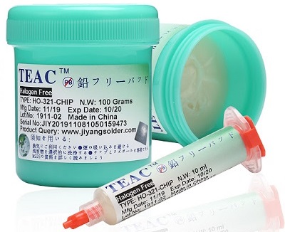
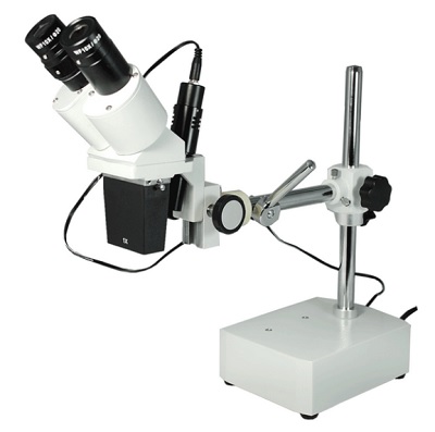
Figure 6 - Solder Flux When joining two metals in a soldering process, like used in PCB assembly, flux is required to achieve a true metallurgic bond. That ensures the solder joint doesn’t crack or come loose even with the day-to-day wear-and-tear. This article covers the types of fluxes available, the advantages and disadvantages of each, and options for flux removal. Flux is a chemical compound that helps prepare the metal surfaces for soldering by removing oxides, promoting wetting, and enhancing the flow of solder. It typically comes in the form of a paste, liquid, or core within the solder wire. The flux compound contains active ingredients, such as rosin or organic acids, that react with the oxides on the metal surface. When heated, the flux activates and starts to remove the oxides, preventing them from interfering with the soldering process. The flux also promotes wetting, which is the ability of the molten solder to spread and adhere to the metal surfaces. By reducing the surface tension of the solder, flux ensures that it flows smoothly and evenly, creating strong and reliable solder joints. Additionally, flux helps prevent the re-formation of oxides during soldering by creating a protective barrier on the metal surfaces. This barrier shields the freshly cleaned metal from the surrounding atmosphere, preventing rapid oxidation and ensuring a clean and reliable solder joint. Magnifying glass The ultimate helping hands for your workspace! Ideal tool for working on PCB's. Unfortunately, where the PCB components are present, the ICs are also included, the magnifying glass is obligatory. I use the binocular one which is much better. For more details see Figure 7 below
Figure 7 - Magnifying Glass
Microscope Camera (optional) For those who often work on micro SMD circuits, the micro camera is very important, because it is possible to see directly on the 9 or 7-inch monitor what happens on the board, without using micro binoculars or a lens. The micro camera is also used to inspect the circuits and record everything that happens during the repair, and maybe show your customer what has been done on their device (Max support for 32G micro SD cards, micro SD card and TF card reader are not included) The display can be rotated 270°, giving you a comfortable viewing angle. Support image switching: On the 7 inch microscope, the image shows simultaneously. Normally, image of endoscope is smaller than 7'' microscope. Press the down button, the image will switch to 7 inch image. The model used is: Andonstar AD206S LCD Digital Microscope with Endoscope for Soldering 7 inch. For more details see Figure 8 below
Figure 8 - Micro camera and Microscope
Soldering procedure for component Quad Flat Pack Method 1 QFP chips have existed for some time now, but due to the complexity of the chip, its high pin count, and the easily warped materials it is made of, removal tends to do more damage, than good. The repair aspect of this guide will cover some of the simple techniques to force chip functionality once again, even if it is for a few moments to determine point of failure in a system. When it comes to removal, you must be mindful of all nearby components, as many that lead to these type of chips are extremely small, with a low heat tolerance (I learned this the hard way). Also recall that not all PCB's that mount these chips are single layered, the reverse side may also have an array of chips that my literally fall off while heating components for removal. This guide will be described Step by Step to avoid any missing understanding Note: IT IS NOT ADVISED TO USE THIS METHOD IF YOU HAVE MULTIPLE (SMALL) COMPONENTS NEARBY Step 1 (Component Removal) Identify the location of the IC to be installed or removed if there are other components nearby. Once you are sure there are no components near the chip, apply the metal shield, Install the Miniature suction cup on the chip, and prepare the heat gun from solder station (hot air gun) see Figure 2 Above (The metal cup for this method is mandatory) Step 2 (Component Removal) First off, begin by placing the cup you have or some aluminium foil on the PCB, surrounding the chip. Once the chip is cupped or isolated, you can turn on your heat gun, and set the heat to 750 degrees. This may seem overkill but will allow you to heat the chip up in a matter of seconds. The heat gun will use a large amount of power, so if you have typical incandescent bulbs it will likely flicker, this is fine, but do not put any further load on your circuit. Let the gun heat up, you can check this, if it does not have an indicator, by using a thermometer and placing it on the metal tip of the gun. Once heated, place your suction cup attached to your tweezers and place it on the chip. Aim your heat gun down, place the heat gun as show in the image, going around the cup until you can feel some slack in the chip. Make sure not to move the chip while it is only slack, in this case you may end up pulling pins off, or removing lines inside the PCB. Lightly pull directly upward and allow the chip separate from the board. You have successfully removed the chip! For more detail see Figure 9 below
Figure 9 - Chip Extraction Step 1 (Installation) At this stage for chip installation, I recommend not using the hot air gun (the high-temperature chip could be damaged) but using simple solder with some preparation
Figure 10 - Chip Installation Conclusion For beginners, this method is not recommended, especially if you are dealing with expensive mainboards. Before carrying out this work it is advisable to carry it out as training on other broken boards, the first thing to be successful in this work is not the tools but the operator's manual skills. Remember, during the soldering phase, the chip it must not move (mandatory) Method 2 This method is for those who only have a soldering iron available. For more details see Dynamic Figure 12 below
Figure 12 - Chip removal by soledering only Method 3 This Method is for those who own the air hot gun and the Miniature suction cup system (do it yourself). For more details see Dynamic Figure 13 below
Figure 13 - Chip removal by air hot gun and Miniature suction cup Note: This operation is very dangerous because there are other electronic components (capacitors) nearby. Before doing this operation, it is advisable to cover the components near the chip with aluminium adhesive to prevent them from being damaged. Recommendation
Figure 14 - Cleaning the connections All the material included in the BK8000 desoldering station is available here on the website. We also have a desoldering paste and trichloroethylene for cleaning printed circuit boards. For any questions do not hesitate to contact us |


+(39) 347 051 5328
Italy - Kazakhstan


09.00am to 18.00pm
About
We offer the best and economical solutions, backed by 27+ years of experience and international standards knowledge, echnological changes, and industrial systems.
Our Services
Marketing Materials


Marketing Materials1


