
|
IR2101 H Bridge DC Motor Driver Circuit
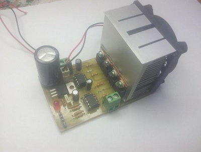
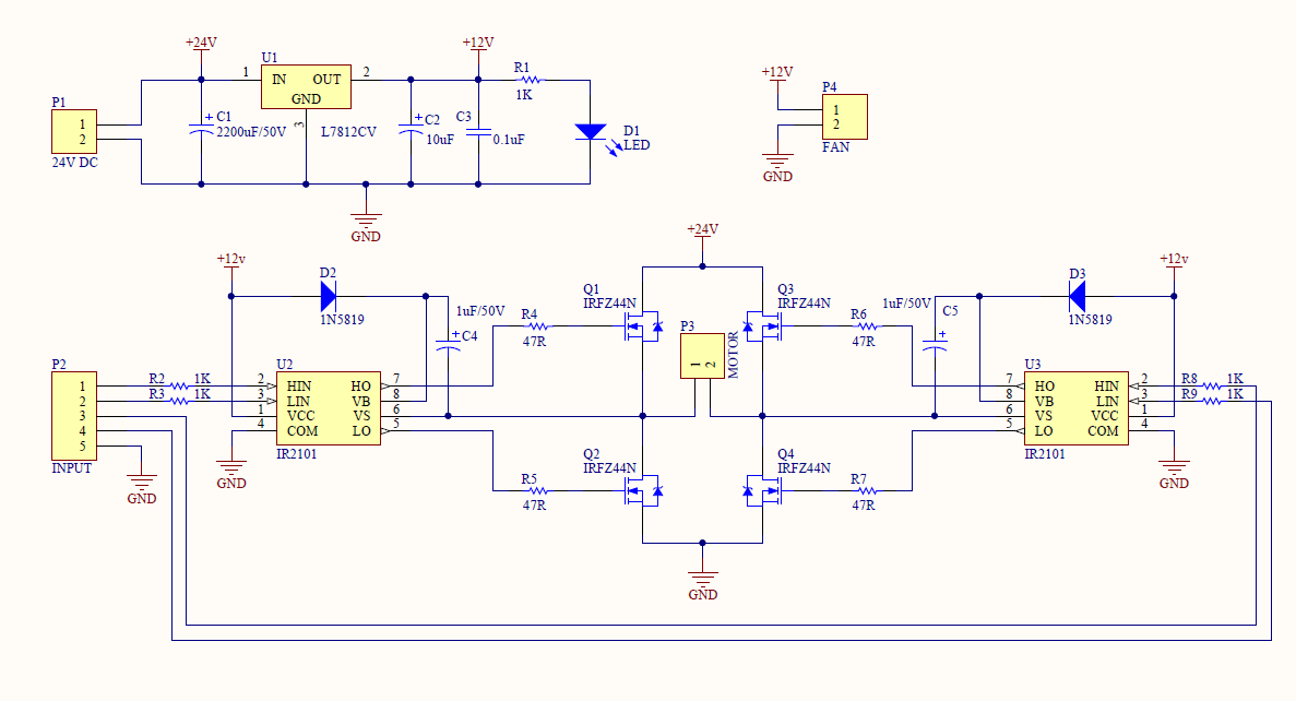
As you can see from the Figure above, the circuit is equipped with a large heat sink and a fan attached for cooling. Without this, the MOSFETs will overheat and damage easily. So the heat sink is really very important IR2101 Motor Driver Circuit Diagram
The power supply is for 12 V, but you can supply it up to 20 Volts (as per datasheet). The IR2101s are powered via the 7812 income regulator. So 12V and maximum. Be careful not to exceed the input voltage. You can apply 20V which is the maximum voltage of IR2101. Do not apply more than 20V power, it will be damaged immediately. The MOSFETs used are the IRFZ44N As a control, has been used a PIC18FJ which controls all the steps of the motor. In the test carried out on this circuit, a PIC18 was applied as mentioned which, is connected to the RS232 port, and through the program, regulates the speed of the motor through the PC. Come test e stato usato il simulatore Proteus. This circuit was implemented on a tomato machine, with some modifications it turned out to be an excellent circuit. As for the PCB board, we build it (minimum request 5 pieces). All components including the controller (PIC18) and ASM Code are available here. For any clarification, don't hesitate to contact us.
|

+(39) 347 051 5328
Italy - Kazakhstan


09.00am to 18.00pm
About
We offer the best and economical solutions, backed by 27+ years of experience and international standards knowledge, echnological changes, and industrial systems.
Our Services
Marketing Materials


Marketing Materials1


