
|
HIP4081A High Power H Bridge Motor Driver
The high-power H-bridge circuit designed to control permanent magnet DC motors. It was designed expressly as a motor control for robot combat in competitions such as BattleBots™ and the like. However, the attributes of a controller for such an environment are suitable for a wide range of commercial or industrial motor control applications. The OSMC can drive a wide variety of motors and other loads and is easy to mount and interface to a variety of microcontroller units. The low-cost is also easy to modify or repair if needed. Specifications and Features
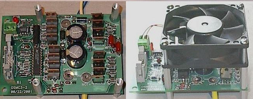
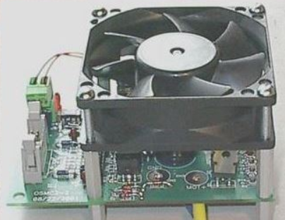
Unlike most motor controls, this type does not use a heavy heatsink to extract heat from the MOSFETs. Rather, it uses a cooling fan to blow air across the board. This removes heat more quickly than a plate-type heatsink and has lower weight. The fan itself is a commonly available 80mm square computer cooling fan. Either a 12V or 24V fan may be installed on this circuit. Mounting holes are provided at the correct spacing to mount the fan directly over the MOSFETs for maximum cooling efficiency. For more details see Figure 1 below
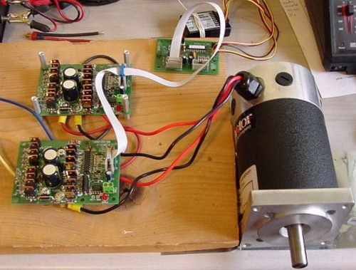
Figure 1 - Cooling Fan The Circuit is a simple H-bridge power amplifier. It does not have any on-board logic to interpret RC or other commands. An external logic interface is required to translate command inputs into the PWM signals needed to drive the board. This increases system complexity somewhat but also increases flexibility as the board may be driven by any microcontroller or other signal source that can provide PWM and Enable logic, in fact, this circuit has been modify and apply a Microcrontroller from MICROCHIP (PIC24FJ128GA010). One of the major advantages of separating the power section of the controller from the logic interface section is to allow the power units to be paralleled for special applications. One exciting application of this is to use two boards on a single interface channel to control high-powered four-brush motors such as the MagmotorTM or AstroflightTM motors. By using a special interface cable the board can control these 4-brush motors at twice the current of a single power unit. That gives a continuous current capability of over 300A! Figure 2 below shows a µMOB controlling 2 boards driving a four-inch Magmotor. Stall testing with this motor and 24V of Hawker batteries showed no appreciable heating of the boards.
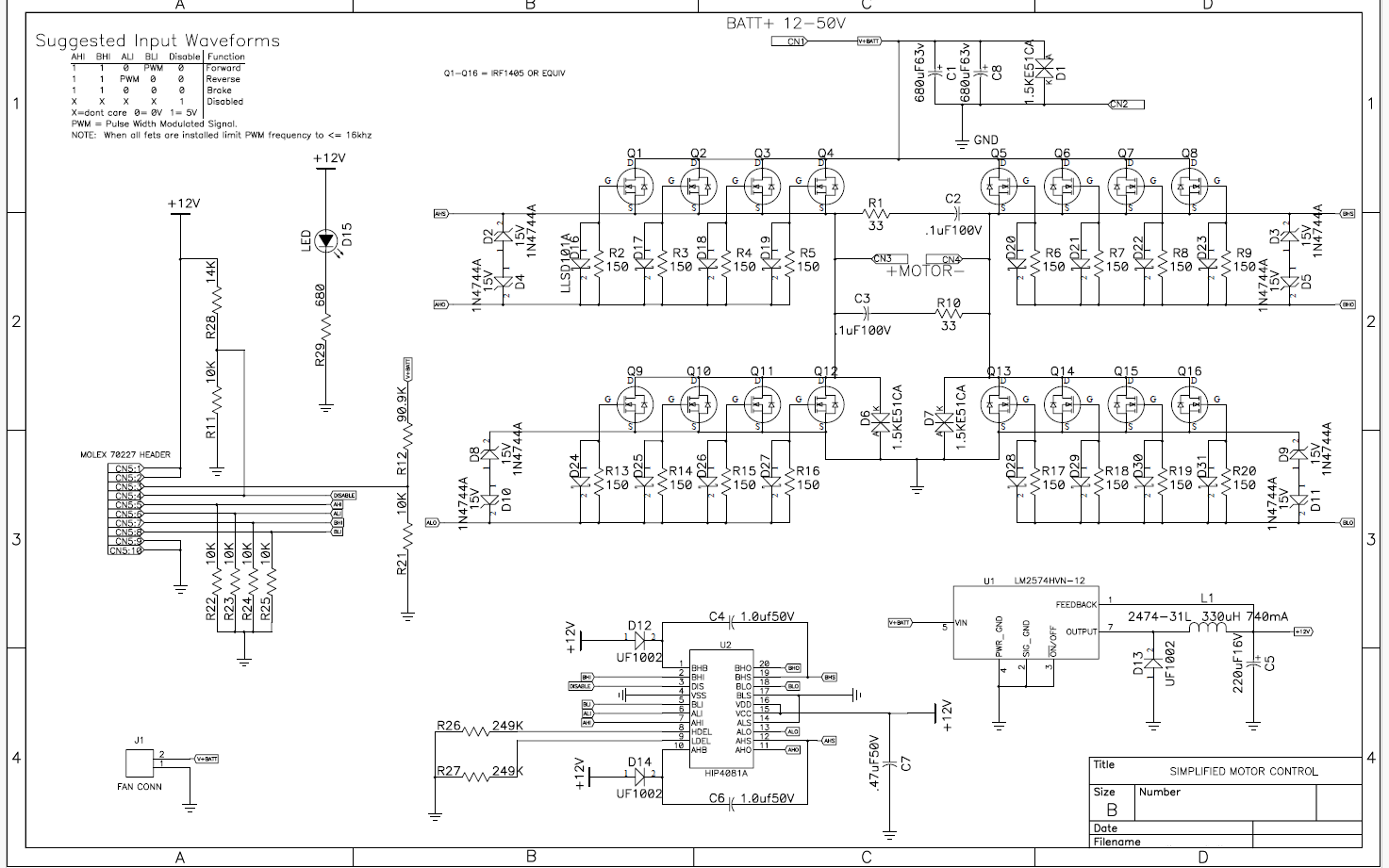
Figure 2 - CC Motor Circuit Diagram
The circuit can be driven with 1-5 volts pulse, but through our tests we managed to make the system work with 4-20mA via the PIC24 of the microchip Components List
The circuit is really with strong power, and also very reliable. But, if the motor remains running for too long the MOSFETs begin to overheat too much, but this depends on the application where they are installed. This type of circuit has been installed on 46" motorised valves. For protection, we have installed a circuit which cuts the power in case the temperature of the MOSFET increases. For now these valves are controlled via 4-20mA and have no issue. As for the PCB board, we build it (minimum request 5 pieces). All components including the controller (PIC24) and ASM Code are available here. For any clarification, don't hesitate to contact us.
|
||||||||||||||||||||||||||||||||||||||||||||||||||||||||||||||||||||||||||||||||||||||||||||||||||||||||||||||||||||||||||||||||||||||||||||||||||

+(39) 347 051 5328
Italy - Kazakhstan


09.00am to 18.00pm
About
We offer the best and economical solutions, backed by 27+ years of experience and international standards knowledge, echnological changes, and industrial systems.
Our Services
Marketing Materials


Marketing Materials1


