
|
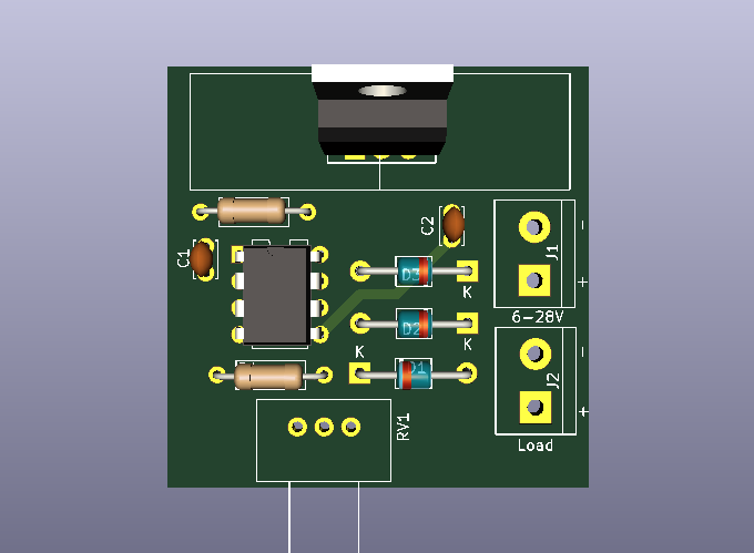
Soft Start Circuit for DC Motors DC motors, in addition to many obvious advantages, have some disadvantages. One of these is a much higher current consumption during startup compared to the current consumed during normal operation, which can overload the power supply. For this reason, the circuit must be calculated well based on the motor absorption. Electric motors, while having many obvious advantages, also have some disadvantages. Soft Start The schematic diagram of the system is shown in the figure. The 555 timer operates in a typical multivibrator application and produces a square wave with a frequency of about 2.2 kHz and about 85% filling. It consists of resistor R3 and capacitor C5 100NF
Figure 1 - Circuit Bord
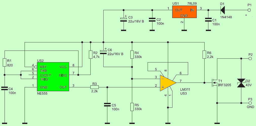
Soft Start Circuit Diagram Figure 2 below shows the complete circuit diagram
The circuit has been simulated with Proteus, for more details you can see Figure 3 below
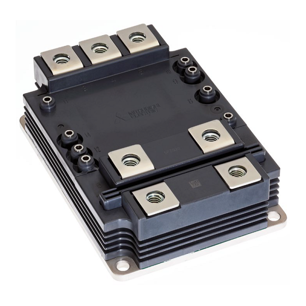
Figure 3 - Simulator Normally, the soft start is used to avoid voltage absorption peaks during motor start-up, this is the reason why the soft start is used. Especially for large industries electric motors. Between the excitation system, the soft start, and the large MOSFETs, they help the motor to rotate slowly during motor start-up (ramp-up) until it reaches the expected rpm and then hooks up to the electrical grid without overloading it. This is the operating principle of all soft starts of electric motors. Figure 4 below shows a large MOSFET, which is used for large motors.
Figure 4 - Large soft start MOSFETs We supply all electronic components, including PCB boards. On request, the circuit can be modified for large motors up to 500 amps. For more details, do not hesitate to contact us
|

+(39) 347 051 5328
Italy - Kazakhstan


09.00am to 18.00pm
About
We offer the best and economical solutions, backed by 27+ years of experience and international standards knowledge, echnological changes, and industrial systems.
Our Services
Marketing Materials


Marketing Materials1


