
|
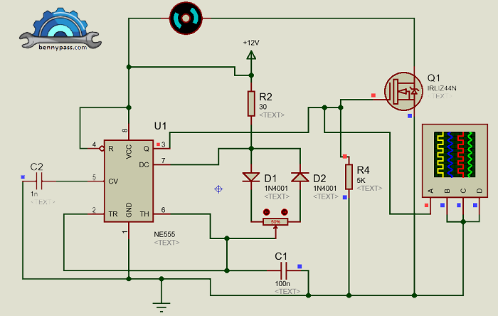
555 PWM Circuit with Motor (DС) The 555 timer is one of the most popular integrated circuits for hobbyists. And one of the cool features is its ability to produce a PWM signal. The circuit is fairly easy to make, and it can control many things, including motor speed and LED brightness. For more details see Figure 1 below Figura 1 - Circuit Diagram Note: For VCC, you can use anything from 5V to around 15V. What to choose will depend mostly on the size of the motor you are using. If it is small, you can control everything with 5V.
Components list
Note: RVP1 is the trimmer that regulates the speed. The set value is 10KΩ, but if you want to increase the speed of the motor, just increase its value, for example, 47KΩ. How the PWM 555 Circuit Works The PWM 555 Circuit is known as an improved 555 oscillator. This is because it makes use of a couple of extra components to improve the output signal that the most common astable multivibrator circuit would give. It uses R1 and C1 to control the frequency of the signal. And you can modify the duty cycle with RV1. The downside with this circuit is that the frequency of the output also varies quite a bit, which means it does not work well with servo motors that require a specific frequency. If you need a specific and stable frequency, check out this project on controlling a servo motor with the 555 Timer. The circuit can also be tested with the simulator, for more details, see Figure 2 below
Figura 2 - Circuit Simulator For more details about this circuit including electronic components and main board, contact us here on the website |


+(39) 347 051 5328
Italy - Kazakhstan


09.00am to 18.00pm
About
We offer the best and economical solutions, backed by 27+ years of experience and international standards knowledge, echnological changes, and industrial systems.
Our Services
Marketing Materials


Marketing Materials1


