
|
STAR – DELTA Connection
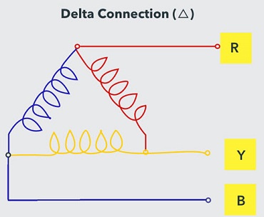
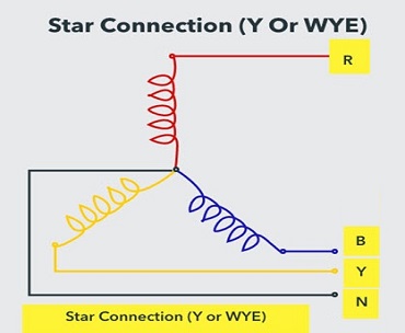
Difference Between Star And Delta Connections
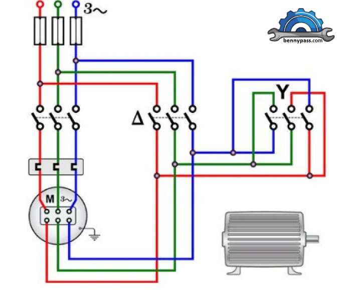
STAR – DELTA Starter The Star Delta starter is the most basic starting method for minimizing the inrush starting current of an induction motor. For typical operation, the starter can be utilized with all squirrel-cage induction motors that are delta connected. The decrease of the high motor current reduces the motor’s starting torque. Star-delta starting is thus particularly ideal for drives that are not loaded until after starting. The starting time is longer than with direct starting, which is noticeable when driving higher inertial loads. For more details see Figure 3 below
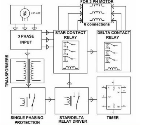
Figure 3 - Star-Delta Connection including devices To limit starting current, a reduced voltage starter is required to start a large motor. The star delta starter is a lower voltage starter that applies 1/√3 voltage during the starting process. Star Delta Starter Components The following are the primary components of a wye-delta starter:
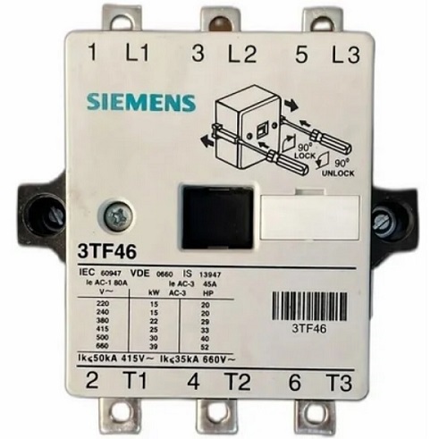
Figure 4 - Components Installation Contactors A contactor is a high-current-rated heavy-duty relay used to power the induction motor. Contactors have current ratings ranging from 10A to several hundred amps.
The main contactor & delta contactor are AC3 type and rated at 58% of the motor’s current rating. During the operation of the induction motor, these contactors are closed.
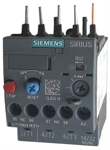
Figure 5 - Contactor A star contactor, on the other side, only carries star current when the motor is turned on. Because the starting current is 1/3 the rated current, the star contactor can be of the AC3 type and 33% of the full load current rating. Because these contactors only control winding current, which is 33% of the full load current in the star delta starter, the three contractors used in the star delta starter are smaller than the single contactor used in the DOL starter. Overload Relay As with induction motors, the majority of winding failures are caused by overloading, operating on an unbalanced voltage supply, and single phasing owing to phase loss, which can lead to excessive heating and motor winding insulation degradation.
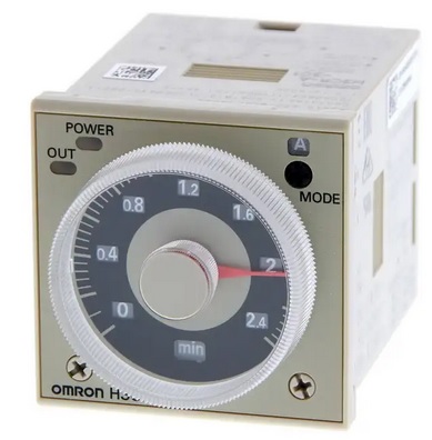
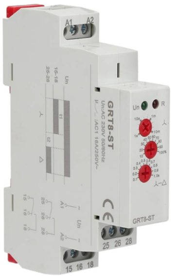
Figure 6 - Overload Relay To prevent windings against overloading and short-circuiting in the internal winding, overload protection is required. As a result, the 3-pole thermal overload relay prevents all of these circumstances. Timer The timer in the wye-delta starter’s fundamental function is to switch the contactor from star to delta when the motor reaches almost 80% of full load speed.
Figure 7 - Omron Timer
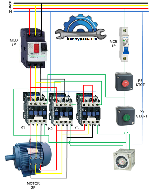
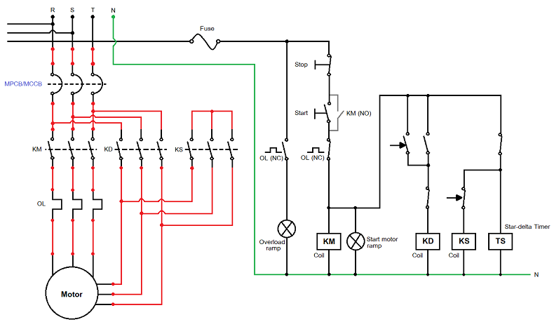
The fuse unit Three fuses are connected in series with the motor circuit to protect it against external overcurrent and short circuit faults. In addition, one fuse is used to protect the wye-delta starter’s control circuit. MCB A circuit breaker is an electrical switch that operates automatically to protect an electrical circuit from harm caused by excess current from an overload/short circuit. Its primary function is to interrupt current flow when a problem is identified. In addition a fuse, which can only be used once before needing to be replaced, a circuit breaker can be reset to resume regular operation. Push-button Start (NO) This is an open (NO) type push button that is used to start the motor. Push button Stop (NC) This is an NC type push button for stopping the motor. Star-Delta Starter Circuit Diagram and Working Principle The diagram illustrates the connection of a three-phase induction motor with a star-delta starter. The star-delta starter is a common type of starter that is widely used to start squirrel cage induction motors. It is used to start a squirrel cage induction motor that is meant to function normally on a stator winding that is delta linked.
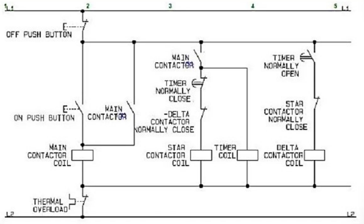
Figure 8 - Star-Delta Starter Circuit Diagram The stator windings are connected in star when the switch S is in the START position. When the motor reaches 80% of its rated speed, the changeover switch S is thrown to the RUN position, connecting the stator windings in the delta.
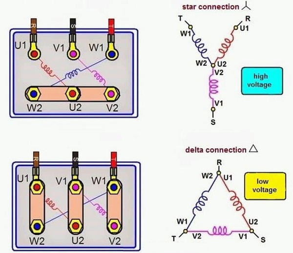
Figure 9 - Classic Circuit Diagram The line current generated by the motor at starting is decreased to one-third of the starting current with the windings linked in delta by connecting the stator windings first in star and then in delta. When the stator windings are connected in a star at the start, each phase receives a voltage equal to 𝑉𝐿/√3, where VL is the line voltage. Stator windings are connected in a star connection, and when speed hits 80%, it flips from star to delta using a triple pole double throw (TPDT) switch. Consider the following:
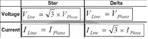
The winding current per phase (IPS) equals supply line current (ILS) since the winding is star-connected. IPS=ILS Due to the star connection, the voltage across the winding’s individual phases is VL/√3 Thus, each phase winding current equals IPS =VL/√3Z Since the supply line current (ILS) and the winding current per phase (IPS) are equal in this case, we may generate, IPS = VL/√3Z↔ILS = VL/√3Z Let’s now examine the condition in which the motor is started using the same three-phase supply terminals and a delta-connected stator winding. Consider the following:
Figure 10 - Star-Delta Starter Circuit Diagram Due to the delta-connected winding, the supply line current (ILD) is equal to 3 times winding current per phase (IPD). ILD= √3IPD The voltage across the winding’s individual phases is because the winding is delta connected. VL Consequently, each phase winding current is IPD= VL/Z Now that can be expressed as, ILD= √3IPD= √3VL/Z By comparing the currents drawn from the supply line by an induction motor with the star & delta-connected winding, we are able to obtain the following: ILD/ILS= √3VL/Z/VL/√3Z=3 ILS= (1/3)ILD Thus, in the case of a star delta, the starting current from the primary is one-third that of direct switching in delta. (Starting torque in a stator winding motor with a star connection) /(Starting torque in a stator winding motor with a delta connection) =(VL/√3)2/VL2=1/3 According to the equation, the starting torque generated by the DOL starter is reduced to one-third by the star delta starter. The star-delta starter can be considered as a 57.7% tapping autotransformer.
Transient States of Star Delta Starter The operation of a star delta starter can be simply understood using three different states: Star connected state During the start-up process, the main contactor and star contactor will be near together to complete the power circuit. In this state, the induction motor stator winding will be connected in star, reducing the voltage across the motor winding to 1/3 of the line voltage. When the motor reaches 80% of its full load speed, the timer circuit disconnects the star contactor first and then connects the delta contactor to the circuit. Open transition state Delta connected state Star-Delta starter Types
Manual Star-Delta Starter The Manual Star Delta Starter is an ideal choice for oil mills, flour mills, and agricultural industries. Superior design by a contractor, with a transient Star Position, assures a smooth transition. Semi- Automatic Star-Delta Starter Semi-Automatic Starter (SASD) is a time-tested and extremely reliable starter that is ideal for a wide range of agricultural and industrial applications. It protects the motor from overload, single phasing, phase reversal, and severe unbalanced voltage circumstances. Automatic Automatic Star Delta Starters have three contactors, an overload relay or circuit breaker, and a timer for setting the Star position (starting position). The Star Delta Starter requires a motor to be in delta connection during normal operation. When the motor is idle, all the rotor bars create a closed route, like a short-circuited transformer. This will increase rotor current flow. Start-up draws 8-10 times the rated current from the stator. Reduce the motor’s voltage before starting it. In a Star connection, the line voltage is three times the phase voltage. So, starting a motor in star reduces voltage and current. In delta connection, the voltage is the same as phase voltage, so the motor receives full voltage. The Star/Delta Starter is comprised of three contactors, a pneumatic timer, and a thermal overload relay or circuit breaker for 440-volt, 50-Hz 3 phase motors. Star-Delta starter (motor starting) Characteristics
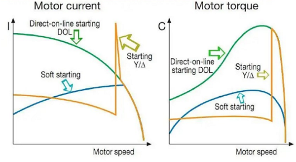
Figure 11 - Star-Delta starter (motor starting) Characteristics Features of the Star-Delta starter
Advantages of a Star-Delta starter
Disadvantages of a Star delta starter
Application of a Star delta starter
What are the reasons for not utilizing a star delta starter with HT motors? For heavy-duty machinery, HT motors are typically recommended. To do that, a soft start and a high starting torque are required. Wound type induction motors with external resistance are often preference in these conditions.
Figure 12 - star delta starter with HT motors When it comes to a star-delta starter, what is the intended function of the delay? A star-delta starter’s delay is designed to make it easier for high-torque induction motors to move from the star connection which permits lower voltage and, consequently, lower starting current to the delta connection which provides full voltage for the normal operation. The star-delta starter’s delay gives the motor time to attain a specific speed by allowing it to accelerate progressively while in the star connection. The starter converts the motor from star to delta configuration following the delay period. The motor can function well and deliver the necessary torque for its intended use by switching to full voltage & full power in a delta connection.
Figure 13 -delay system A star-delta starter’s delay essentially provides a smooth and regulated transition from low voltage starting to high voltage operation, enhancing motor performance and shielding it from unexpectedly high currents during starting. |

+(39) 347 051 5328
Italy - Kazakhstan


09.00am to 18.00pm
About
We offer the best and economical solutions, backed by 27+ years of experience and international standards knowledge, echnological changes, and industrial systems.
Our Services
Marketing Materials


Marketing Materials1


