
|
AC Motor Control Basics An AC motor controller is known as a device that controls the speed of the AC motor. An AC controller can also be referred to as a variable frequency drive, adjustable speed drive, frequency converter and more. The AC motor receives power, which the AC motor controller converts into an adjustable frequency. This adjustable output allows the motor speed to be precisely controlled.
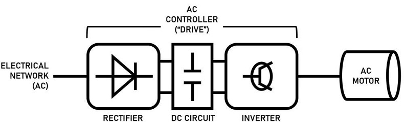
Figure 1 -Motor control speed Diagram
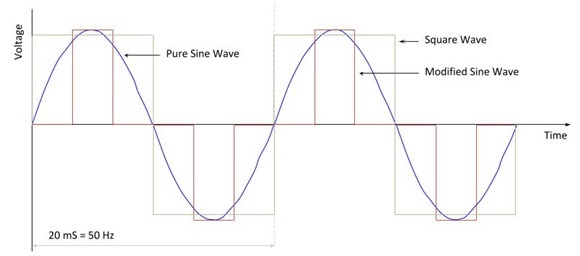
What are AC Motor Controllers? The operation of AC motors is explained thoroughly in our article on induction motors and is a good review on how AC motors convert electromagnetism into useful mechanical energy. How do AC Motor Controllers work? As previously stated, AC controllers convert an input AC frequency into a DC current that simulates an AC frequency, which can then be set by the user, thus controlling the speed of the motor. This is accomplished using three main components: a rectifier, an inverter, and a DC circuit that connects the two. There are also methods for increasing the slip of an AC motor, which will change the speed of rotation in relation to the AC frequency, thus controlling speed. Increasing the slip can be done by either varying the resistance through the motor coils (variable series resistance, see our article wound rotor motors), or varying the voltage to the coils (variable voltage transformers); however, AC drives are more commonplace, as they are more modular and have been engineered to give the user precise digital control over their motor without using integrated components such as resistors or rheostats in the motor windings. Types of AC motor controllers There are some common ways in which AC drives take incoming AC current and transform it into a simulated, controllable frequency. In each method, the goal is to allow operators to input frequency commands to the stator RMF, and as such change the rotation speed of the rotor. There are three main methods for doing this: variable voltage inversion (VVI), pulse-width-modulation (PWM), and flux vector drives. Variable Voltage Inversion In this method, the AC frequency of the power source is rectified to a DC current, which is then increased and decreased in discrete steps to imitate a sine wave (or how a true AC current oscillates). This way, operators can regulate these steps to effectively change the motor speed, and these are commonly referred to as six-step inverters (though different steps exist). Figure 2 below shows an example of how a VVI controller sends stepwise power to a motor, simulating a true sine wave:
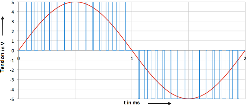
Figure 2 - Voltage over time graph representing how VVIs allow speed control in AC motors Note: Notice that, if more steps were added, it would give a better approximation to the true sine wave. Pulse-Width-Modulation Pulse width modulator circuits, or PWMs, are a popular method to simulate AC oscillations, as they often provide more precise control than variable voltage inverters. They do so by rapidly switching the current (or “pulsing” it) to match the area under the curve of the true sine wave. Recall from calculus that the integrals of any two continuous graphs are equal if their areas under their curves are equal; the goal of PWM is to more accurately approximate the area of a sine wave using many pulses of voltage, and the density of these pulses will dictate the size of the simulated sine wave (and thus change the motor speed). Figure 3 visualizes these spikes on a voltage over time graph:
Figure 3 - PWM graph compared to a true sine wave Note: Notice how the pulses change frequency as they move along the sine wave, but do so in an orderly, equidistant fashion. Vector flux Flux vector drives not only vary the frequency of the current to change the speed of the motor but can also change the motor’s torque as well. They can do this by taking advantage of the motor’s magnetic flux (the number of magnetic field lines passing through a surface, in this case, the coils) as a portion of the current in all induction motors must generate the magnetic coupling between the rotor and stator. The remaining current is the portion that generates torque, and flux vector drives hold the coupling current to a minimum while allowing operators to adjust this torque-producing current. This is easier said than done, as controlling both torque and flux current is analytically intensive, and requires continuous transformations between coordinate systems. Flux vector drives, therefore, require microprocessor-based controllers, software, and oftentimes encoded sensors to precisely tune the independent currents. These drives typically provide speed accuracy of up to 0.3%, and while more impressive than the other two options, comes at a heavier installation and operational cost. Applications and Selection Criteria AC motor controllers have upgraded traditional AC motors, and have allowed them to serve functions in even more areas of industry. One of the most common areas where AC drives are implemented is in HVAC systems, specifically in fans, pumps, and blowers. Designers can optimize the airflow through a building by electrically signaling these components to quickly increase or decrease their speeds, conditioning the building with more efficiency, and saving the owner money on such costs. They also save manufacturers from excess wear and tear on their motors, as AC drives regulate the inrush of starting current, which can damage the motor over repeated cycles of successive starting and stopping. They pair well with integrated motor systems, and anyone looking to control many motors at once should seriously consider AC motor controllers.
Taking some time to seriously consider these questions will not only help you to find a better suited AC drive but also to optimize its performance at a reasonable cost. |

+(39) 347 051 5328
Italy - Kazakhstan


09.00am to 18.00pm
About
We offer the best and economical solutions, backed by 27+ years of experience and international standards knowledge, echnological changes, and industrial systems.
Our Services
Marketing Materials


Marketing Materials1


