|
Pure Sine Wave Inverter driver board (IR2110)
This is the latest generation inverter thanks to the digital chip EG8010, they function very well by bringing their own dead-time control of pure sine wave inverter generator chip, used in two-stage DC-DC-AC power conversion structure or single-stage DC-AC power frequency transformer Boost architecture, an external 12MHz crystal oscillator, to achieve high precision, and harmonic distortion is very small, 50Hz or 60Hz pure sine wave inverter ASIC. The chip uses CMOS technology, the internal integration of the SPWM sine generator, dead time control circuit, the multiplier factor range, soft start circuit, protection circuit, RS232 serial communication interface and a serial LCD driver module 1602 functions. Depending on requirements, this circuit can be built with 300, 900, or 2500 watts
The circuit is based on the EG8010 chip, Figure 1 below shows it
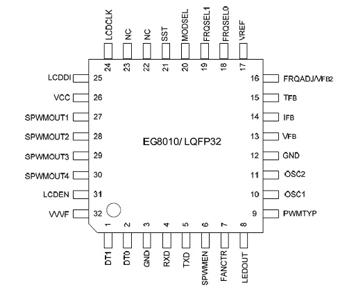
Figure 1 - EG8010 chip
Figure 2 below shows the Block Diagram
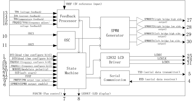
Figure 2 - Block Diagram
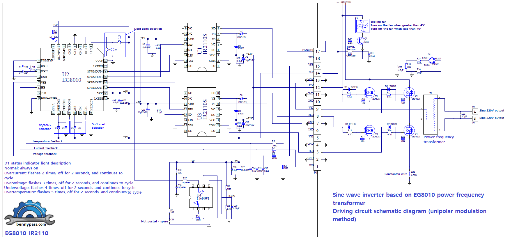
Circuit Diagram
There are different operating philosophies, each with its characteristics. For more details see the list below
- EG8010+IR2110S Sinusoid inverter(unipolar modulation)
- EG8010+IR2110S+Cross-conduction prevention logic Sinusoid EG8010+IR2106S Sinusoid inverter (unipolar modulation)
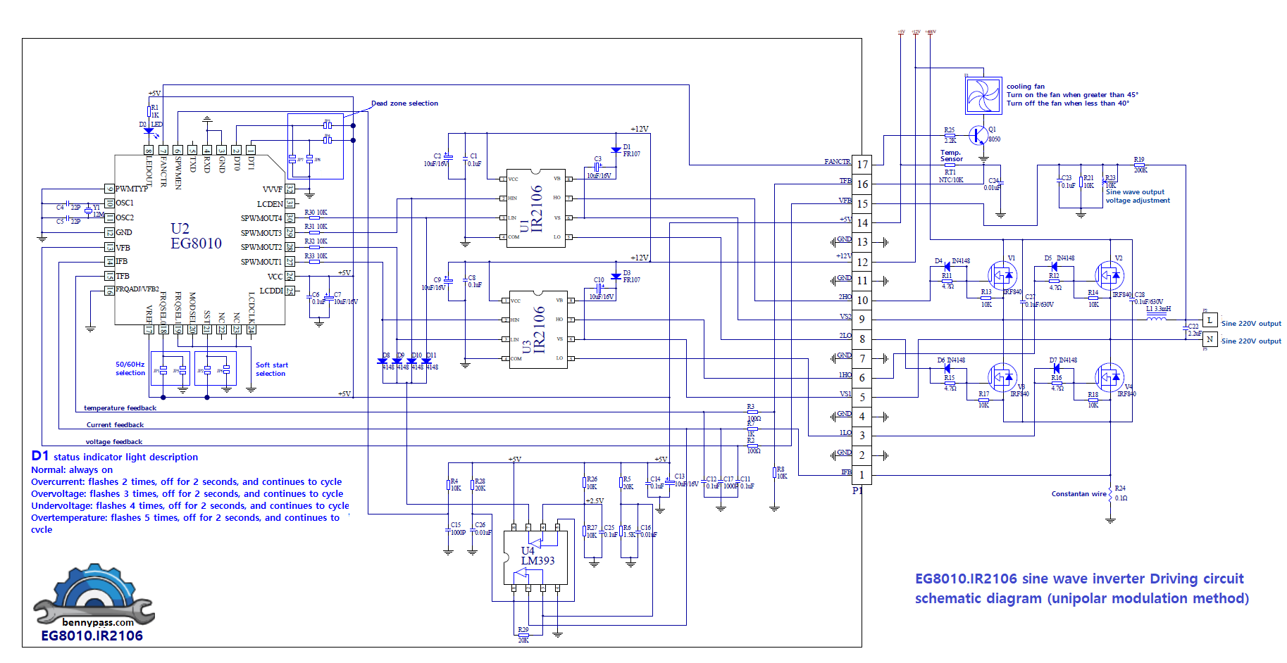
- EG8010+IR2106S Sinusoid inverter (unipolar modulation)
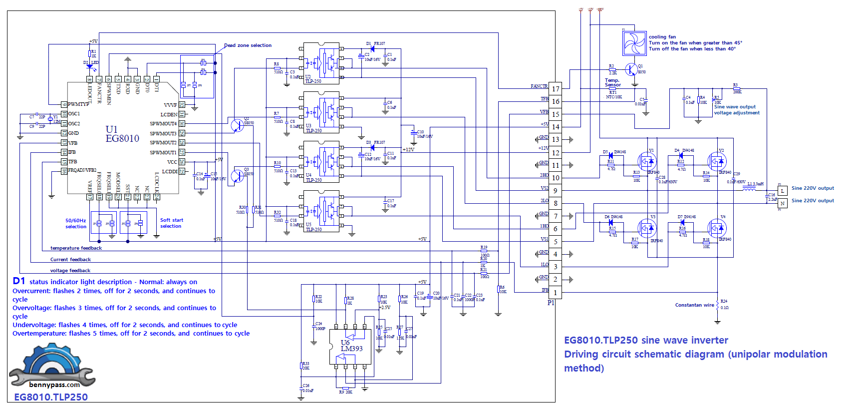
- EG8010+TLP250 Sinusoid inverter (unipolar modulation)
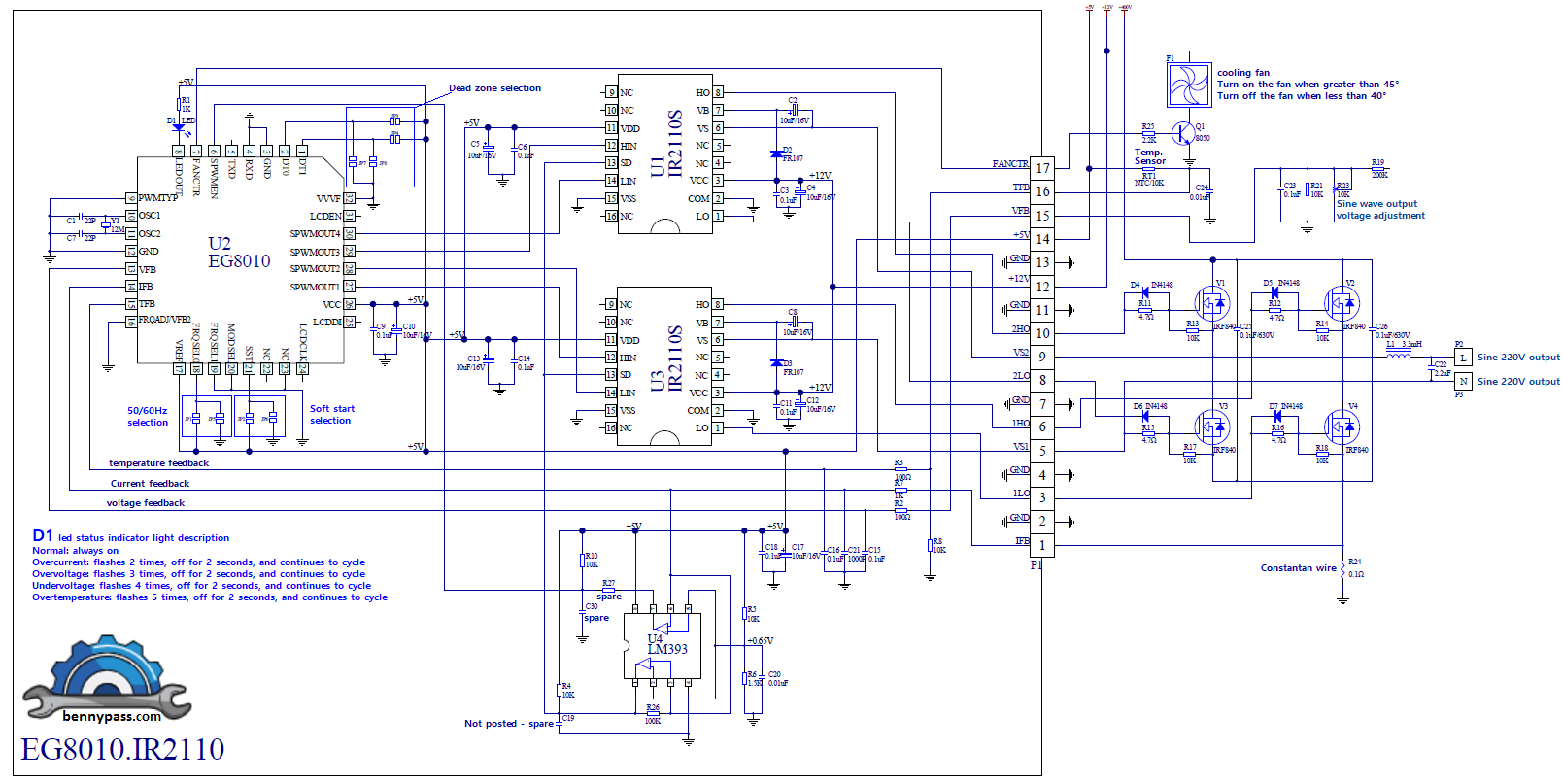
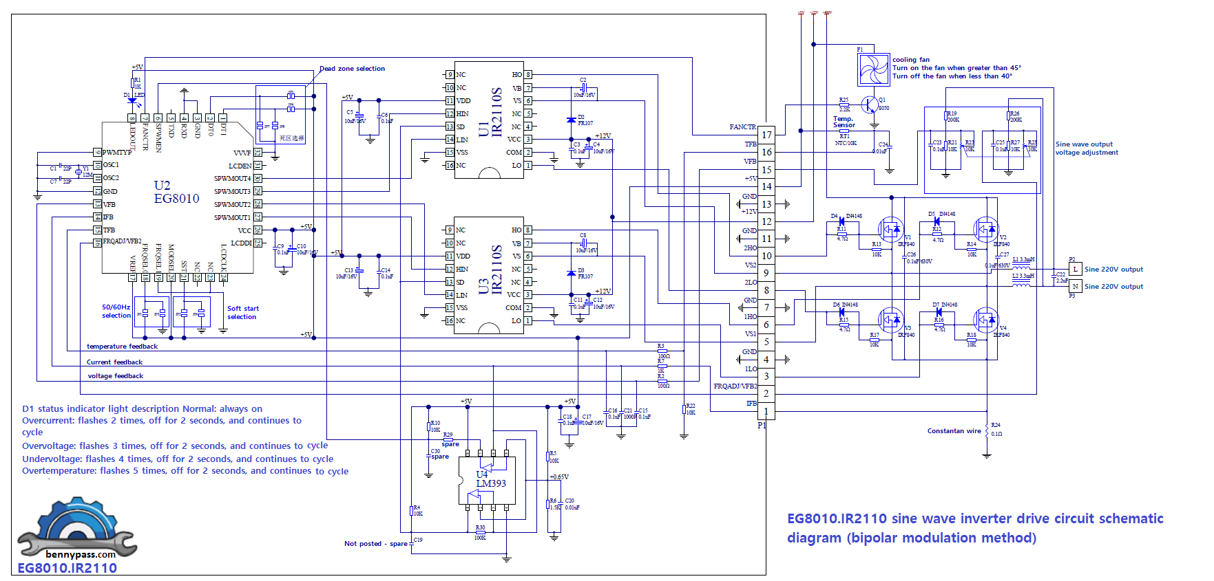
- EG8010+IR2110S Sinusoid inverter (bipolar modulation)
- EG8010+IR2110S Sinusoid inverter (low power frequency transformer)
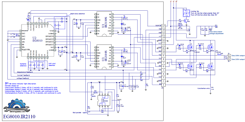 Figure 3 - EG8010+IR2110S Sinusoid inverter(unipolar modulation) Figure 3 - EG8010+IR2110S Sinusoid inverter(unipolar modulation)
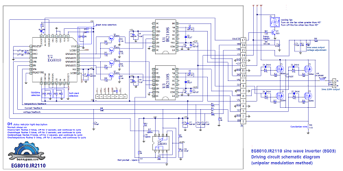 Figure 4 - EG8010+IR2110S+Cross-conduction prevention logic Sinusoid EG8010+IR2106S Sinusoid inverter (unipolar modulation) Figure 4 - EG8010+IR2110S+Cross-conduction prevention logic Sinusoid EG8010+IR2106S Sinusoid inverter (unipolar modulation)
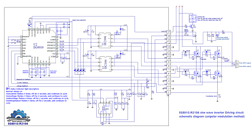 Figure 5 -EG8010+IR2106S Sinusoid inverter (unipolar modulation) Figure 5 -EG8010+IR2106S Sinusoid inverter (unipolar modulation)
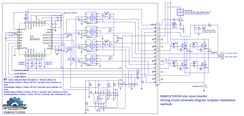 Figure 6 - EG8010+TLP250 Sinusoid inverter (unipolar modulation) Figure 6 - EG8010+TLP250 Sinusoid inverter (unipolar modulation)
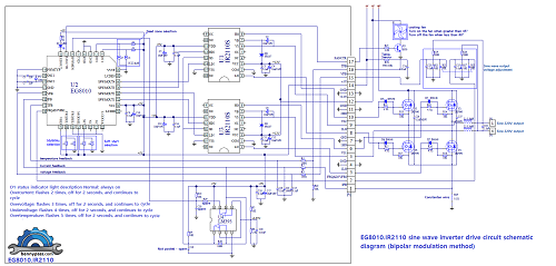 Figure 7 - EG8010+IR2110S Sinusoid inverter (bipolar modulation) Figure 7 - EG8010+IR2110S Sinusoid inverter (bipolar modulation)
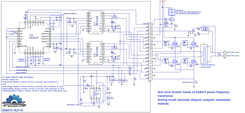 Figure 8 - EG8010+IR2110S Sinusoid inverter (low power frequency transformer) Figure 8 - EG8010+IR2110S Sinusoid inverter (low power frequency transformer)
Serial 12832 LCD Setting
EG8010 supports 12832 LCD modules. It can display the inverter’s voltage, frequency, temperature and current information to the user. Figure 9 shows how to connect EG8010 with 12832 LCD.
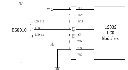
Figure 9 - EG8010 Serial 12832 LCD
Technical Specifications:
- 5V single power supply
- 4 pin set of pure sine wave output frequency:
- 50Hz pure sine wave of fixed frequency of 60Hz pure sine wave of fixed frequency 0-100Hz
- pure sine wave frequency adjustable 0-400Hz pure sine wave frequency adjustable
- Unipolar and bipolar modulation
- Comes with deadband control, pin 4 dead time:
- 300nS dead time 500nS dead time 1.0uS dead time 1.5uS dead time
- External 12MHz crystal oscillator
- PWM carrier frequency 23.4KHz
- Voltage, current, real time temperature feedback
- Overvoltage, undervoltage, overcurrent and overheating protection
- Soft-start mode pin setting the response time of 1S
- Serial communication to set the output voltage, frequency and other parameters
- External Serial LCD Module 1602 displays the in
Feature
- +5V single supply
- 4 settingsofoutput frequency can set by 2 pins
- 50Hz constant frequency sine-wave
- 60Hz constant frequency sine-wave
- 0-100Hzadjustable frequency sine-wave
- 0-400Hz adjustable frequency sine-wave
- 2 modulation modes can set by1 pin
- Unipolar modulation
- Bipolar modulation
- 4 settings of dead time can set by 2 pins
- 300nS
- 500nS
- 1.0uS
- 1.5uS
- External 12MHz crystal oscillator
- 23.4KHz Modulation frequency
- Output Voltage \ Current \ Temperature detect and handle
- 3 seconds soft start can select by 1 pin
- USART communication support
- Voltage \ Current \ Temperature \ Frequency Display support by external LCD
- Parameters and functions customize sup
Applications:
- Single phase pure sine wave inverter
- PV Inverter
- Wind power inverter
- Uninterruptible Power Supply UPS System
- Digital generator system
- IF power
- Single-phase motor speed controller
- Single-phase inverter
- Sine wave dimmer
- Sine wave regulator
- Sine wave generator
Diffrence between Unipolar and Bipolar Inverter
Unipolar and bipolar pulse-width modulation (PWM) inverters are both used in power electronics to control the output voltage of inverters. The main difference between the two lies in the way they modulate the width of the pulses.
In a unipolar PWM inverter, the width of the pulses is modulated only in one direction, either positive or negative, resulting in a unipolar output waveform. This means that the output voltage swings only in one direction from the reference zero voltage.
On the other hand, in a bipolar PWM inverter, the width of the pulses is modulated in both positive and negative directions, allowing the output voltage to swing above and below the reference zero voltage. This results in a bipolar output waveform.
The choice between unipolar and bipolar PWM inverter depends on the specific requirements of the application, such as the need for bidirectional power flow or the desired output waveform characteristics.
Conclusion
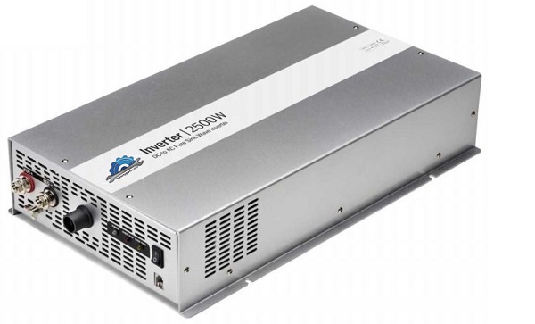
This is truly the latest generation inverter, reliable and compact. We supply all the electronic components inside including the PCB boards (minimum order 5), or you can directly purchase the inverter already assembled with its aluminum casing
|