
|
Data Store Buffer seal
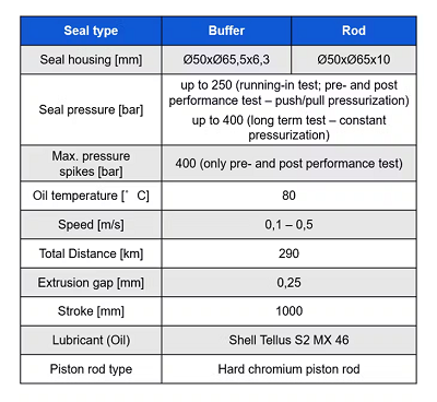
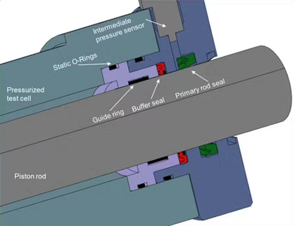
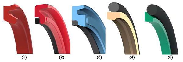
The test-rig consisted of a pressurized test cell, a piston rod, an electrical drive and a hydraulic pressurizer. The hydraulic oil had a viscosity class of 46. An additional pressure sensor was installed between buffer and primary rod seals to investigate possible intermediate pressures. Test Protocols During verification testing, five buffer seals were examined:
The following performance criteria were considered and analyzed during or after testing:
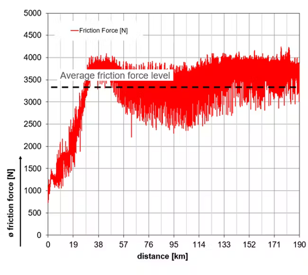
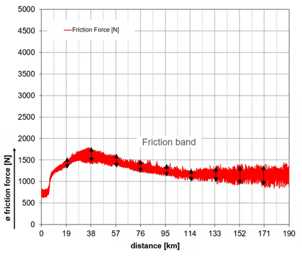
The seals’ friction force levels and bands The friction level and band should be minimized to improve long-term performance. High friction levels increase temperatures, which shortens seal life. The height of the friction band indicates how well the primary rod seal is lubricated.
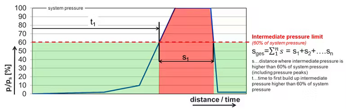
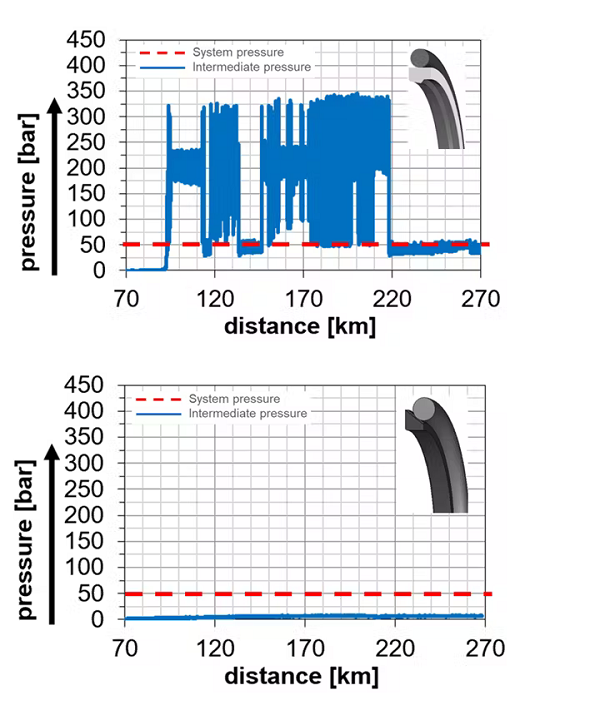
This graph above shows the ratio of intermediate pressure to system pressure over distance and time. If the ratio is above 60%, the buffer seal will not absorb pressure spikes Intermediate pressure between buffer and primary rod seal Buffer seals must prevent intermediate pressure build-up to protect the primary rod seal. In heavy-duty applications, pressure spikes can exceed 600 bar and should be handled by the buffer seal. The primary rod seal is often a U-cup made of polyurethane; it handles pressures up to 400 bar. Therefore, the overall distance where intermediate pressure is higher than 60% of the system pressure and the time to build up intermediate pressure were analyzed. Visual analysis of buffer and primary rod seal before and after testing Our team looked at wear and extrusion on the seal, as well as discoloration. The before-and-after comparison provides direct evidence of seal performance. For example, if the buffer seal is not working properly and there’s evidence of leaks, the primary rod seal will show high extrusion due to intermediate pressure. And if there’s discoloration at the sealing lip of the primary rod seal, the buffer seal was too tight and did not allow enough lubrication to get to the primary rod seal. Leaks Generally, oil that escapes from the hydraulic cylinder into the environment must be kept on a minimum level. Recall that the chances for leaks increases as the ratio of outstroke to instroke piston-rod velocities increases. In addition, the primary rod seal needs good back-pumping ability. This is important for the buffer and primary rod seals. The tests were done in four phases:
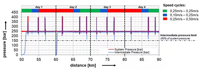
The testing parameters include several different pressure and piston rod velocity cycles, with pressures and piston rod velocities set so that pressure was low when speed was high and vice-versa. This mimics an operating excavator; the high loads are mostly at low operating speeds, and the higher speeds go with low loading. Test Results
Lip seal without back-up ring The graph above shows the system and intermediate pressure curve of seal #11 at the pre-performance test. It is clearly visible that the intermediate pressure increases immediately. Over 96% of the entire testing distance, intermediate pressure equaled the system pressure which means no buffering capability is available.
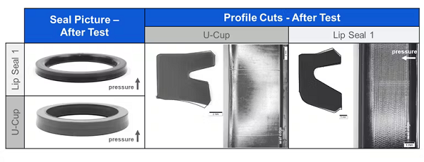
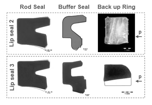
The above images show damage to the seal’s profiles. The buffer seal didn’t show any major damage. But the primary rod seal already shows some wear and extrusion after a testing distance of 90 km. The seal did no work as expected.
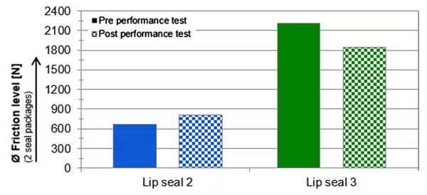
4 and 5. O-ring energized glide ring seals The above figure graphs chart friction level of glide ring seal 4 and 5 at pre- and post-performance test as well as profile cut analysis after the whole verification test.
The graphs above show intermediate pressure at 50-bar of backstroke system pressure during the long-term test for both 4 and 5 glide ring seals. Seal 4 immediately built-up intermediate pressure to a multiple system pressure level, the result of no venting capability. Seal 5 shows no to low intermediate pressure built-up at several pressure stages between 50 and 400 bar.
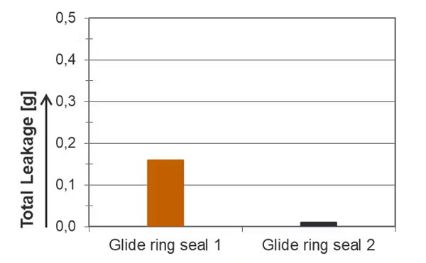
Here’s a comparison of leaks with Seals 4 and 5. The good performance of Seal 5 improves the performance of the entire rod seal package; it had far fewer problems with leaks than Seal 4. This document was taken from: Thomas Schwarz is manager of testing, materials technologies & research; Wolfgang Swete is manager of product technology and development; Silvio Schreymayer, is manager of testing; Martin Wallner is the manager or product development; Emmanuel Pichlmaier is a product development engineer; and Michael Liebminger is a testing engineer for SKF Seals. |

+(39) 347 051 5328
Italy - Kazakhstan


09.00am to 18.00pm
About
We offer the best and economical solutions, backed by 27+ years of experience and international standards knowledge, echnological changes, and industrial systems.
Our Services
Marketing Materials


Marketing Materials1


