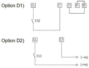
Interlock

The interlock inputs can be used to inhibit the actuator movement in the open or closed direction. The controls are momentary; the inhibiting action continues while the relevant signal is present. The interlock controls work when the local selector is in LOCAL or in REMOTE. The ESD control overrides the interlock controls.

The following options can be configured:
Interlock OP: active when signal is PRESENT, active when signal is ABSENT,
no action (OFF).
Interlock CL: active when signal is PRESENT, active when signal is ABSENT,
no action (OFF).


  Interlock connection diagram
interlok   interlok1 


Configuration procedure

  • Move the local selector to OFF and then simultaneously press OPEN and STOP. Select the language and then enter the password according to the instructions (see entering the set-up mode). When the message displayed is “SET-UP MODE OK?” press YES. Press YES to select the “Actuator Setup” menu, press NO to scroll through the list of available routines, and then press YES to select “INTERLOCK”.
  • Press YES if the configured value of the Open Interlock is correct (PRESENT, ABSENT, OFF). If not, press NO to change it and then press YES.
  • Press YES if the configured value of the Close Interlock is correct (PRESENT, ABSENT, OFF). If not, press NO to change it and then press YES.

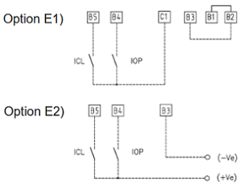
In other words, the interlock function protects the opening or closing of two valves simultaneously. This BIFFI function is not well known by Engineers but can be really important for some systems where this type of function is requires. In addition, it is possible b electronic configure an ESD function that activates the valve to go into open or close position quickly (depending from configuration).

An example of interlock function is shown in figure below by two contactors. The function of BIFFI actuators is same but via electronic

interlok2

 Fail-Safe Action

This function configures the actuator action if loss of the 4 - 20 mA input or bus signals occurs. This action only takes place if the local selector is in REMOTE and if the positioning function or the bus interface are active. When the 4 - 20 mA or bus signal is restored, the XTE3000 resumes normal functionality. The Interlock and ESD controls override the Fail-Safe action according to table below:

 OP/CL controls  Fail-Safe action Interlocks   ESD
 Lowest priority  Highest priority


interlok3

Configuration procedure

  • Move the local selector to OFF and then simultaneously press OPEN and STOP. Select the language and then enter the password according to the instructions (see entering the set-up mode). When the message displayed is “SET-UP MODE OK?” press YES. Press YES to select the “Actuator Setup” menu, press NO to scroll through the list of available routines, and then press YES to select “FAIL-SAFE”.
  • Press YES if the configured ACTION is correct (open, close, stay-put, go to position xxx%, off). If not, press NO to change it and then press YES.
  • Press YES if the configured value of the DELAY is correct (from 0 to 255 seconds). If not, press NO to change it and then press YES.

For those who use the bus communication, this functionality is very important in case the bus will fail and valve required to return in safe position open or close or stay put (no action).


favicon bacd

+(39) 347 051 5328

Italy - Kazakhstan

09.00am to 18.00pm

About

We offer the best and economical solutions, backed by 27+ years of experience and international standards knowledge, echnological changes, and industrial systems.

Marketing Materials

Spring Renovation
Industry
US Gas Company
Construct
Plus Project
Vam Drilling Service
X Project
X Project
Cabrrus Training

Marketing Materials1

Spring Renovation
Industry
US Gas Company
Construct
Plus Project
Vam Drilling Service
ultrasonic sensor
ultrasonic sensor
Cabrrus Training