
|
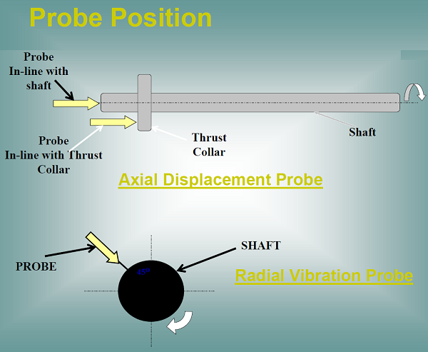
Proximity sensors (Displacement, Velocity, and Acceleration Sensors) Proximity probes are used to detect both radial vibrations and axial displacement of the rotor. These probes should be firmly secured to the compressor casing and should be positioned close to the shaft for accurate readings. For more details see Figure 1 below
Figure 1 - Probe Position Practically, the sensor measures continuously the distance between the shaft and sensor head, then indicate if this distance will change in positive or in negative (if distance increase or decreases). For more details see Figure 2 below
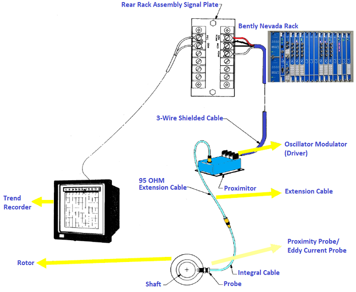
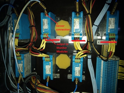
Figura 2 - Sensing Signal All the components required for this measurement are visible in Figure 3 below.
Figure 3 - Vibration Monitoring System
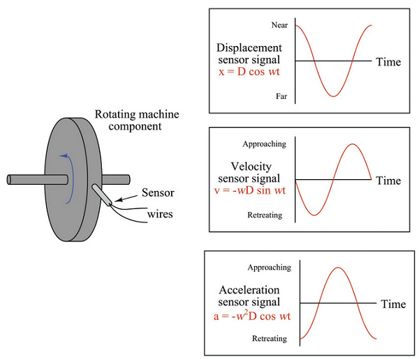
Axial Displacement Probe & Radial Vibration Probe Sensors used to measure vibration come in three basic types: displacement, velocity, and acceleration. Displacement sensors measure changes in distance between a machine’s rotating element and its stationary housing (frame). Displacement sensors come in the form of a probe that threads into a hole drilled and tapped in the machine’s frame, just above the surface of a rotating shaft. Velocity and acceleration sensors, by contrast, measure the velocity or acceleration of whatever element the sensor is attached to, which is usually some external part of the machine frame. For more details see Figure 4 below
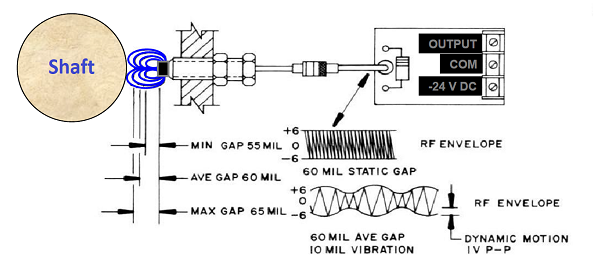
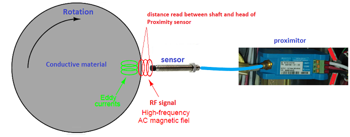
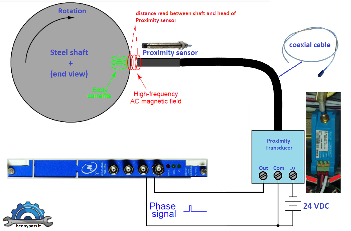
Figure 4 - Types of measurement A design of displacement sensor manufactured by the Bently-Nevada corporation uses electromagnetic eddy current technology to sense the distance between the probe tip and the rotating machine shaft. The sensor itself is an encapsulated coil of wire, energized with high-frequency alternating current (AC). The magnetic field produced by the coil induces eddy currents in the metal shaft of the machine, as though the metal piece were a short-circuited secondary coil of a transformer (with the probe’s coil as the transformer primary winding). The closer the shaft moves toward the sensor tip, the tighter the magnetic coupling between the shaft and the sensor coil, and the stronger the eddy currents. The Proximitor contains electronics that provide two functions
The figure 5 below shows the entire loop
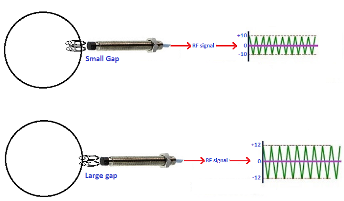
Figure 5 - Detection Loop When a conductive material is present in the RF field, Eddy Currents flow in the surface of that material.
Figure 6 - Small Gap and Large Gap For more details about the unit mils and table of metal conductivity click here. Once the probe is close enough to cause eddy currents to flow in a conductive material the RF signal is affected in two ways:
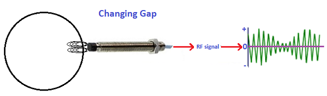
Regarding Gap changing, please see Figure 7 below
Figure 7 - Gap changing If the target is moving SLOWLY within the RF field, the signal amplitude INCREASES or DECREASES SLOWLY.
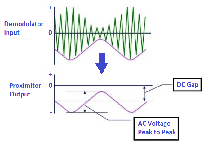
Figure 8 - Proximitor Output The demodulator circuit deals with slowly or rapidly changing signal amplitude in the same way. If the target is not oscillating, as might be the case with a thrust probe, the Proximitor output is a constant DC voltage, called the gap. If the target is oscillating (gap changing slowly or rapidly) the Proximitors output is a varying DC voltage (AC) shown above by a sine wave. If the probe is observing a vibration, the Proximitor will provide both a DC (gap) and an AC (vibration) component in the output signal. A typical system frequency response is from 0 Hz (DC) to 10 kHz. Newer transducer systems, such as the 3300XL proximity system have responses up to 12 kHz. Types of Transducers
The proximity transducer system consists of three parts
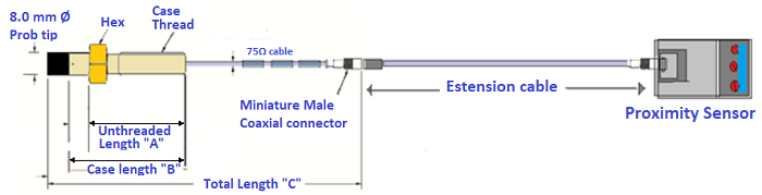
Figure 9 below shows the entire loop with all components Figure 9 - Proximity Transducer and Proximity sensor with all accessory Figure 10 below shows a typical connection of the Proximity Sensor
Figure 10 - Typical Connection of the Proximity Transducer Proximity Transducer performs two functions: converts the mechanical vibration to an electrical signal proportional to the displacement of vibration. Figure 11 below shows the Proximity Transducer, Proximity sensor, and Bently Nevada card. Bently Nevada Card convert the signal from Proximity Transducer in value for the control system.
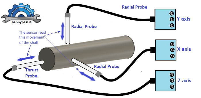
Figure 11 - Typical connection of the Proximity sensor Figure 12 below shows an typical connection with radial vibration and axial displacement on the shaft
Figure 12 - Radial and Axial Displacement sensors Figure 13 below shows the Radial Sensors connection
Figure 13 - Radial Sensors connection
Figure 14 below show the Axial Displacement Sensors
Figure 14 - Axial Displacement Sensors Figure 15 below Shows the kew Phasor Sensor (senor speed)
Figure 15 - kew Phasor Sensor For further information, read the following articles |

+(39) 347 051 5328
Italy - Kazakhstan


09.00am to 18.00pm
About
We offer the best and economical solutions, backed by 27+ years of experience and international standards knowledge, echnological changes, and industrial systems.
Our Services
Marketing Materials


Marketing Materials1


