|
Understanding Flanges
Understanding flanges is essential for anyone working with piping systems, as they play a crucial role in the system's overall functionality and safety. Flanges serve as connection points that allow for easy assembly, disassembly, inspection, and maintenance of various pipeline components. Knowledge of flange standards, such as ANSI, ASME, and DIN, helps ensure compatibility across different systems and applications. Each flange has specific pressure ratings, known as classes, which denote the maximum pressure it can withstand, ranging from low to high-pressure environments. Selecting the appropriate flange requires assessing factors such as material compatibility, pressure, temperature conditions, and environmental exposure. Proper understanding and selection can prevent potential issues such as leaks, corrosion, and mechanical failure, making flange knowledge integral to the successful operation of piping networks.
How you make a pipe-flange connection varies. It depends on the type and the requirements of your piping system. Some are weld-on pipe flange, while others can be screwed on. The type of flange you choose will also depend on issues such as pressure capacity and application. But first, let’s look at common flange types.
Pipe-flange types
While specialty pipe flanges are available, there are six main types. Here they are, along with how to secure the flange on a pipe.
| Threaded flanges |
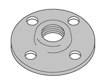 |
They’re used in low-pressure systems on smaller pipes with thick walls. They also make it easy to connect and disconnect pipe systems without disrupting the entire system for maintenance or to make adjustments. To attach the flange on a pipe, the bore’s female thread is screwed onto the pipe’s external threads. These flanges are not welded on.
Typical use:
- Flammable, hazardous or explosive applications where welding is dangerous
- Ideal in restricted spaces where welding flange to pipe can’t be carried out
|
| Socket weld flanges |
 |
The simple design is intended for small-size and high-pressure piping that do not transfer highly corrosive fluids. Socket weld flanges are attached by inserting the pipe into the socket and applying one fillet weld around the outside of the flange. First, the pipe is inserted in the socket of the flange. When it reaches the bottom of the flange, the pipe is lifted out slightly by 1/16" (1.5mm) and welded. This gap allows for thermal expansion created by welding, minimising the probability that the weld will crack. Not suitable for highly erosive or corrosive applications, as the gap is vulnerable to corrosion between the pipe end and the socket’s shoulder.
Typical use:
|
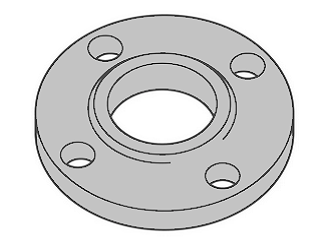
| Lap joint flanges |
 |
Slides over the pipe and used with a stub end. Also known as loose-ring flanges, and back-up flanges. These flanges are used on piping fitted with lapped pipe or with lap joint stub ends. With the stub end, the lap joint flange is typically used in systems requiring frequent dismantling for inspection and cleaning. Another advantage is its ability to swivel and align with bolt holes. As the flange never comes into contact with the fluid, the flange is highly durable and can be re-used.
The use of lap joint flanges in combination with stub ends is a cost-effective solution for stainless steel or nickel alloy pipelines, as the material of the lap joint flange can be of a lower grade (generally carbon steel) than the material of the stub end (which has to match the pipe grade, as in contact with the conveyed fluid).This arrangement, therefore, has these two advantages:
- Reduces the overall cost of the pipeline’s flanged joints, as the use of higher-grade materials is minimized
- Bolting operations are simplified, as the lap joint flange can be rotated around the pipe to help with bolt alignment.
Not recommended in extreme or high-pressure temperature applications.
Typical use:
- Low-pressure applications
- When flange needs frequent dismantling for maintenance
|
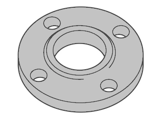
| Slip-on flanges |
 |
These low-pressure flanges are thinner than most other flanges. With an inside diameter slightly larger than the pipe’s outside diameter, the flange slips onto the pipe. A fillet weld is applied at the top of the flange and at the bottom. The welds enhance strength and prevent leakage. Also known as hubbed flanges. Installation of slip-on pipe flanges is easy and therefore low cost.
The speed at placing the flange on the pipe saves costs, but those savings are reduced with the additional costs of two fillet welds which are needed for proper installation.
Key Features
- Ease of Installation: Slip-on flanges are easier to align than weld neck flanges, making them suitable for applications where the precise alignment is challenging.
- Welding Requirements: Requires less welding compared to weld neck flanges. The welding process involves welding around the outer diameter of the flange to secure it to the pipe and may include welding the inside diameter for additional strength and leak prevention.
- Cost-Effectiveness: Generally, slip-on flanges are more cost-effective than weld neck flanges due to their simpler design and reduced material usage.
- Versatility: They can be used with both seamless and welded pipes and are available in a variety of materials, including carbon steel, stainless steel, alloy steel, and more, to suit different applications.
Applications
Slip-on flanges are commonly used in lower-pressure and non-critical applications, such as water distribution, heating and cooling systems, and various piping systems within commercial and light industrial settings. They are not recommended for high-pressure or high-temperature applications or for systems with a high risk of fatigue due to bending forces.
Advantages
- Cost Efficiency: Less material is required for manufacturing, and the simpler design translates to lower costs.
- Simplified Installation: The ability to easily slide the flange onto the pipe before welding simplifies the installation process, especially in tight spaces.
- Flexibility: Suitable for various piping materials and applications where the conditions do not demand the high integrity of a weld neck flange.
Limitations
- Lower Strength: Slip-on flanges have a lower pressure and temperature rating compared to weld neck flanges, limiting their use in high-pressure applications.
- Risk of Leakage: While less common, the potential for leakage exists if not properly welded on both sides.
Installation Considerations
When installing slip-on flanges, it’s important to ensure proper alignment before welding and to follow appropriate welding procedures to secure the flange to the pipe. Both the inside and outside welds are crucial for the structural integrity of the connection and to prevent leaks.
A slip-on flange is connected to the pipe or the fittings by two fillet welds, one executed inside and one outside the cavity of the flange.
The bore size of a slip-on flange is larger than the outside diameter of the connecting pipe, as the pipe has to slide inside the flange to be connected by the execution of a fillet weld.
Slip-on flanges are also defined as “Hubbed Flanges” and they are easy to recognize due to their slim and compact shape.
WELD NECK VS SLIP-ON FLANGE
Flanged joints made with slip-on flanges are, in the long run, a bit more fragile than connections made with welding neck flanges (in similar service conditions). This fact, observed several times on oil & gas fields, seems due to the following facts: a welding neck flange features a tapered hub, absent in a socket weld flange, which distributes the mechanical stress between the pipe and the flange more evenly a welding neck joint as only one welding area instead of two (socket weld flange). Another advantage of the welding neck flange is that it can be connected either to pipes and fittings, whereas socket weld flanges suit pipes only. To summarize the differences between slip-on and welding-neck flanges:
- Strength and Integrity: Weld neck flanges offer higher strength and integrity, making them suitable for severe service conditions, whereas slip-on flanges are better suited for lower-pressure and temperature applications.
- Cost and Installation: Slip-on flanges are generally more cost-effective and easier to install but may require more care to ensure a leak-proof seal.
- Application Suitability: The choice between weld neck and slip-on flanges depends on the application’s pressure, temperature, and criticality. Weld neck flanges are preferred for high-pressure and temperature applications, while slip-on flanges are adequate for less demanding conditions.
|
| Blind flanges |
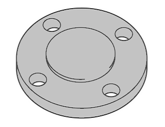 |
The lack of an inner hole enables blind flanges to seal off the end of pipe systems, preventing flow. This makes it easier and more cost efficient to carry out pressure tests. The blind flange connection is also an ideal pipeline flange. You can stop the flow of fluid and safely add new pipes or new lines to the pipeline.
Without blind flanges, shutdowns and repairs would be incredibly difficult to handle. While shutoff valves solve the problem of stopping flow, the location of the valve can be a problem. For example, if the valves are a mile or two away, then you’re looking at a significant amount of wasted fluid.
Blind flanges are installed with bolts, so they’re also easy to remove.
Typical use:
- Testing pipe pressure
- Creating access points to piping systems
- Seal a piping system temporarily to make repairs, or permanently
|
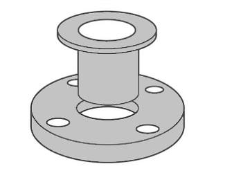
| Welded neck flanges |
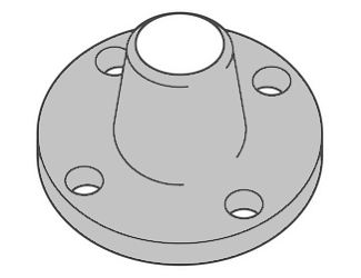 |
Also known as weld bend flanges. Their long necks are butt welded to a pipe. The flange’s bore matches that of the pipe, reducing turbulence and erosion. This flanged connection relocates stress to the pipes, ensuring a decrease in high-stress concentration at the bottom of the flange. When installing, weld neck pipe flanges must be positioned parallel at the time of fitting. Flanges at opposite ends of a pipe should typically have the same bolt-hole direction too.
Design and Features:
- Tapered Hub: The distinguishing feature of a weld neck flange is its gradually tapered hub, which transitions smoothly from the flange diameter to the pipe diameter. This design enhances strength and supports stress distribution.
- Butt-Welded Connection: Weld neck flanges are designed to be butt-welded to the pipe. The welding process creates a continuous metal structure between the pipe and flange, offering superior strength and leak integrity.
- Bore Matching: The bore of the weld neck flange is machined to match the inside diameter of the adjoining pipe, ensuring smooth flow and reducing turbulence and erosion at the joint.
- Pressure Ratings: ASME specifies various pressure classes for weld neck flanges, including but not limited to Class 150, 300, 600, 900, 1500, and 2500. The choice of class depends on the system’s maximum operating pressure and temperature.
Standards
Governed by the American Society of Mechanical Engineers (ASME) under standards such as ASME B16.5 (for sizes up to 24 inches) and ASME B16.47 (for larger sizes), welding neck flanges are manufactured to these specifications to ensure compatibility and safety across a wide range of applications.
Applications
- High-Pressure Systems: Due to their robust design, weld neck flanges are widely used in high-pressure applications, such as steam lines, high-pressure gas pipelines, and power generation plants.
- High-Temperature Services: The integral connection between the flange and pipe makes weld neck flanges suitable for high-temperature applications, including refineries and chemical processing plants.
- Fluctuating Conditions: The strength and dura bility of weld neck flanges make them ideal for systems experiencing fluctuating pressures and temperatures, providing a stable, leak-proof connection.
Advantages
- Strong and Durable: The welded joint provides a strong, high-integrity connection that is less likely to leak compared to other flange types.
- Reduced Stress Concentration: The tapered hub promotes better stress distribution, reducing the likelihood of fatigue and failure.
- High Compatibility: Suitable for a wide range of applications due to the availability of various materials and pressure ratings.
- Low-Pressure Drops: Limited to non-existing pressure drops prevent negative effects such as turbulence and erosion/corrosion of the metals in the proximity of the flanged joints.
- RX Inspections: The tapered hub allows a smooth distribution of the mechanical stress between the pipe and the weld neck flange and facilitates the execution of radiographic inspections to detect possible leakages and welding defects.
|
| Niploflange |
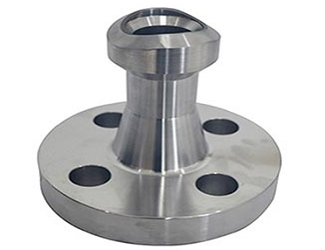 |
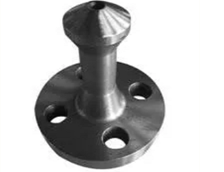
A Nipoflange is used for branch pipelines at 90 degrees and is a product manufactured by combining a welding neck flange with a forged Nipolet.
However, a Nipoflange is a solid single piece of forged steel and not two different products welded together.
To install a Nipoflange, the piping staff has to weld the Nipolet part of the device on the run pipe and bolt the flanged part on the flange of the branched pipe.
Nipoflanges are available in different materials, such as carbon steel ASTM A105 (high-temperature service), ASTM A350 (low-temperature carbon steel), ASTM A182 (stainless steel grades, including duplex and super duplex), and nickel alloys (Inconel, Incoloy, Hastelloy, etc).
Nipoflanges are also manufactured in the reinforced variant, which has additional mechanical strength compared to a standard Nipoflange. |
| Weldoflange |
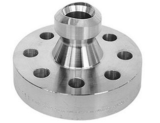 |
A Weldoflange, often referred to as a welding neck flange outlet, is a specialized flange used in the piping industry to create a branch connection from a main pipe. It combines the design features of a welding neck flange with the functionality of a branch connection, allowing for the direct welding of the flange onto the run pipe while providing an outlet for branch connections. This design simplifies the process of creating branch connections, especially in high-pressure and high-temperature applications where reliability and integrity are crucial.
Key Features
- Integrated Design: A Weldoflange consists of a flange with a neck (similar to a weld neck flange) that is directly welded to the side of a pipe. A branch pipe is then connected to the flange, creating a reinforced, leak-proof branch connection.
- High Integrity Connection: The weld between the Weldoflange and the run pipe provides a strong, permanent connection that can handle high pressures and temperatures, making it suitable for critical applications.
- Space-Saving: By integrating the flange and branch connection, Weldoflanges save space compared to traditional tee and flange combinations, making them ideal for tight or congested areas.
Applications
Weldoflanges are widely used in various industrial sectors, such as oil and gas, petrochemical, power generation, and other process industries, where they facilitate the branching off of auxiliary lines from main pipes. Their robust design makes them suitable for: Process piping systems that require reliable branch connections. High-pressure and high-temperature environments where the integrity of branch connections is critical.
Situations where space limitations or system layout constraints necessitate a compact branching solution.
Advantages
- Reliability: Offers a high-integrity, leak-proof connection suitable for severe service conditions.
- Efficiency: Simplifies the piping design by eliminating the need for separate fittings and flanges for branch connections.
- Versatility: Available in various sizes and materials to match the piping system requirements and fluid characteristics.
Installation Considerations
Proper welding techniques are crucial to ensure the integrity of the connection between the Weldoflange and the main pipe.
The selection of Weldoflanges must consider the pressure, temperature, and chemical compatibility of the system to ensure performance and safety.
Inspection and testing of the welded joints are essential to verify the quality and reliability of the connection.
|
| Elboflange |
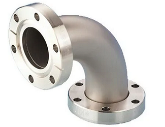 |
An Elboflange is a specialized piping component that combines the functionality of an elbow with that of a flange. Essentially, it is an elbow (a pipe fitting that allows for a change in the direction of the flow) that has an integral flange at one or both ends. This integrated design streamlines the connection of pipes at an angle to equipment, other pipes, or fittings that require a flanged connection, making it a practical solution for various piping system configurations.
Key Features
- Integrated Design: The Elboflange merges two critical piping components into a single unit, reducing the number of required fittings and simplifying the piping layout.
- Directional Change with Flanged Connection: It facilitates directional change in the piping system while providing a ready-made flanged end for bolting to other flanged components, such as valves, pumps, or other pipes.
- High Integrity Connection: Like standalone flanges, the flanged end of an Elboflange is designed to ensure a secure, leak-proof connection when mated with a corresponding flange and sealed with a gasket.
Applications
Elboflanges are used in various industrial settings where piping systems require directional changes and secure, flanged connections, including:
- Oil and Gas: For connecting piping to equipment like compressors, reactors, or tanks where the pipeline needs to turn.
- Chemical Processing: In systems requiring precise control of flow direction and secure connections to process equipment.
- Power Generation: For steam and water lines that need to navigate around obstacles or connect to boilers and turbines.
Advantages
- Simplified Installation: By combining an elbow and a flange, the Elboflange reduces the number of fittings and welds required, simplifying installation and maintenance.
- Space Saving: Ideal for use in tight spaces where combining separate elbows and flanges would be impractical or would create unnecessary complexity.
- Versatility: Available in various sizes, materials, and pressure ratings to suit a wide range of applications and media.
Installation Considerations
- Compatibility: Ensure that the Elboflange material is compatible with the media being transported and the operating conditions (pressure, temperature) of the system.
- Alignment: Proper alignment with the connecting flange is crucial to avoid leaks. The use of appropriate gaskets and bolts according to the flange specifications is essential.
- Inspection and Maintenance: Regular inspection of the bolted connections and gasket integrity is necessary to maintain the system’s safety and reliability.
|
| Latroflange |
 |
A Latroflange is a specialized piping component that combines the features of a lateral tee and a flange. It’s designed to create a branch connection from a main pipe at an angle other than 90 degrees, typically 45 degrees, with a flanged end on the branch. This allows for the direct attachment of equipment, instruments, or additional piping via a flanged connection. The main body of a Latroflange is similar to a lateral tee, facilitating a diagonal flow path, while one end of the branch is equipped with a flange.
Key Features
- Angled Branch: The Latroflange provides an angled branch from the main pipeline, offering a more gradual directional change compared to traditional tees, which can be beneficial for flow dynamics and reducing pressure losses.
- Flanged Connection: The flanged end on the branch allows for easy attachment to other flanged components, such as valves, meters, or equipment, providing versatility in system design and maintenance.
- Integrated Design: By combining the lateral connection and flange into a single unit, the Latroflange reduces the need for multiple fittings and simplifies the piping system layout.
Applications
Latroflanges are used in various industrial applications where a diagonal branch connection with a flange is required, including:
- Process Piping Systems: In chemical, petrochemical, and oil and gas industries for branching out to process equipment or instrumentation.
- Water Treatment: For attaching monitoring equipment or bypass lines in treatment plants.
- Power Generation: In steam and cooling water systems where controlled flow distribution to auxiliary equipment is needed.
Advantages
- Efficient Flow Distribution: The angled branch can help reduce turbulence and minimize pressure drops in the system.
- Ease of Installation and Maintenance: The flanged branch end allows for quick attachment or detachment of components, facilitating easier system modifications, inspections, and cleaning.
- Space Saving: The integrated design saves space compared to using separate fittings and flanges to achieve the same configuration.
Installation Considerations
- Material Compatibility: The material of the Latroflange should be compatible with the fluid being handled and the operating conditions (temperature, pressure, and corrosion potential) of the system.
- Flange Standards: The flange part of the Latroflange must conform to relevant standards (such as ASME B16.5) to ensure proper sealing and compatibility with other flanged components.
- Proper Alignment: Careful alignment with the connecting flange is essential to prevent leaks. Using the appropriate gasket and following specified bolt-tightening procedures are critical for a leak-proof connection.
|
| Swivel Flange |
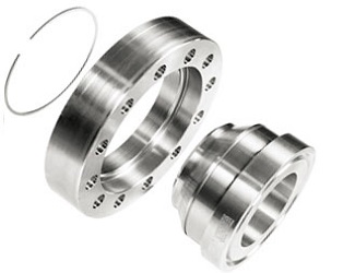 |
Swivel ring flanges facilitate the alignment of the bolt holes between the two mating flanges, a feature that is helpful in many circumstances, such as the installation of large-diameter pipelines, subsea and offshore pipelines, pipe works in shallow waters, and similar environments. Swivel flanges suit oil, gas, hydrocarbons, water, chemical, and other demanding fluids in petrochemical and water management applications.
In the case of a large diameter pipeline, for instance, the pipe is fitted, at one end, with a standard welding neck flange, and with a swivel flange at the other end: by simply rotating the swivel flange on the pipe, the operator can achieve a perfect alignment of the bolt holes in a way easier and faster way.
The major standards for swivel ring flanges are ASME/ANSI, DIN, BS, EN, ISO, etc. The most common standard for petrochemical application is the ANSI/ASME B16.5 or ASME B16.47.
Swivel flanges are available in all the standard shapes of common flanges, i.e. weld-neck, slip-on, lap-joint, socket weld, etc, in all material grades and in a wide dimensional range (sizes can vary from 3/8” to 60” and pressure rating from 150 to 2500).
Swivel flanges can be manufactured in carbon steel (ASTM A105), alloy steel (ASTM A182 F1, A182 F5, A182 F9, A182 F91), and, stainless steel (ASTM A182 F304, A182 F304L, A182 F316, A182 F316L).
|
| Expanding Flange |
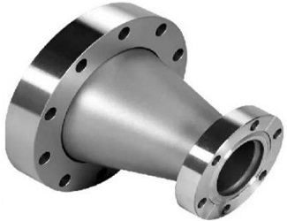 |
Expanding flanges, or “expander flanges”, are used to increase the bore of the pipeline from one specific point to another or to connect pipes to other mechanical devices such as pumps, compressors, and valves that have different inlet sizes.
The expanding flange represented in the picture is a welding neck flange with a larger bore on the non-flanged end.
Expanding flanges can be used to increase the run pipe bore only by one or a maximum of two sizes and not more (for example: from 2 to 3 or a maximum of 4 inches).
Expander flanges are a cheaper (and lighter) solution compared to the combination of a buttweld reducer and a standard flange (which is the standard solution for pipe bore increases above 2 sizes).
The most common materials for expanding flanges are A105 (high-temp. carbon steel), A350 (LTCS), and ASTM A182 (stainless steel and above).
Pressure ratings and dimensions of expanding flanges are by the ANSI/ASME B16.5 specification and are available with raised or flat faces (RF, FF). |
| Reducing Flange (Reducer) |
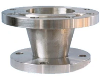 |
Reducing flanges, otherwise called reducer flanges, have an opposite function than expander flanges seen above, i.e. they are used to decrease the bore of a pipeline.
The bore of the run pipe can be safely reduced by only 1 or 2 sizes (otherwise a solution based on the combination of a butt weld reducer and a standard flange has to be used).
Reducing flanges are available in most sizes and material grades, and are not generally available from stock.
Reducing flanges follows the same considerations in terms of specifications, sizes, and material grades as expander flanges.
The last type of forged product that resembles the shape of a flange is the so-called spectacle blind: while not properly a flange, a blind (or a ring spacer or spade) is used in between pipes to isolate the pipeline mechanically and in a very easy way. More details are provided in another section of our Wiki for piping. |
Characteristics of Flanges
Flanges are essential mechanical components that connect pipes, valves, pumps, and other equipment in piping systems, enabling efficient flow and maintenance access. They are typically circular in shape and are characterized by their strength, durability, and ability to withstand high pressures and temperatures. Flanges are available in various materials, including stainless steel, carbon steel, and alloys, each suited for specific applications and environments. Their surfaces are often finished with coatings or treatments to prevent corrosion and ensure longevity, especially in demanding industrial settings. Standard characteristics of flanges include dimensions such as outside diameter, bolt circle diameter, and thickness, which follow specific codes and standards. Proper selection of flange characteristics is crucial for compatibility and efficiency in piping systems. Overall, understanding these features helps in selecting the right flange for optimal performance and safety.
Flange types: at a glance
| Type |
Pressure capacity |
Pipe sizes |
Use for |
| Threaded |
Low |
Small |
Attaching without welding |
| Lap joint |
Low |
All |
Systems that need frequent disassembly |
| Slip on |
Low |
All |
Low installation cost; easy assembly |
| Blind |
Very high |
All |
Flow pressure testing; closing pipes |
| Welded neck |
High |
All |
High-pressure systems; extreme temperatures |
What is flange facing?
 |
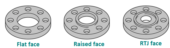
The flange face is the area on the head where your gasket will go. The three most common types are:
- Raised face (RF)
- Ring type joint (RTJ)
- Flat face (FF)
|
Flanges with different faces should not be mated. For example, a raised face to flat-face flange connection will result in leakage from the joint, per ASME code B31.3.
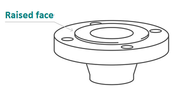
Raised face flanges
The most common type is the raised face flange. Its name comes from the raised gasket surface, above the bolting circle face. The raised face concentrates more pressure on a smaller gasket area. In turn, this increases the joint’s pressure containment capability.
The height of the raised face is determined by the flange’s pressure rating. Likewise, the higher the pressure rating, the bigger the flange diameter, the more bolts needed and the thicker the flange.
Flat face flange
Raised face vs. flat face flange, also called full face flange, isn’t an issue. They play different roles. Instead of a raised face, this is a flat surface. Consequently, the gasket surface is the same plane as the bolt frame, covering the flange from its inside diameter to outside diameter.
- Full face is designed to avoid the bending that flanges undergo as bolts are torqued.
- Cast iron can break during this process, which is why this material is often used to make flat face flanges. The design prevents this problem from happening.
Ring-type-joint face flange
High temperature, high-pressure flanges or rather, flanges used in extreme environments, utilise a ring-type-joint face. These flanges often have a raised face with a ring groove machined into it. They can also have grooves cut into their faces with steel ring gaskets. The flanges seal when the bolts are torqued, compressing the gasket between the flanges into the grooves.
Ring joint flange vs raised face
The purpose behind a raised face flange is to concentrate more pressure on a smaller gasket area, increasing the joint’s ability to contain the pressure. Ring-type-joint face flanges don’t use gaskets. The groove within the flange enables the ring to centre itself when the bolts are torqued. As the process pressure increases, so, too, does the sealing pressure.
Face flanges: at a glance
| Typically used: |
Raised face flange |
Flat face flange |
Ring-type- joint face |
| Process plants (chemical, etc.) |
√ |
|
|
| Oil & gas |
√ |
|
√ |
| Valves |
|
√ |
|
| Cast-iron equipment |
|
√ |
|
| Low-pressure water pipe systems |
|
√ |
|
| Severe applications: high pressure and high temperature (up to 1,382⁰F/ 750⁰C |
|
|
√ |
|


