|
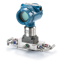
Rosemount™ Coplanar 3051S1CG5A2E11A1AB4M5Q4 + R305EC22BWR3B4L4Q15 Pressure Transmitter
Estimated Shipping Day: Usually ships in 3-4 weeks
Non-Cancelable / Non-Returnable Products. Please review and verify the Part Number/Order Code before buying it.
 Instrument Datasheet Instrument Datasheet
Manifold Datasheet
Technical parameters
Rosemount™ 3051S Coplanar Pressure Transmitter (Gauge).
Part Number: 3051S1TG5A2E11A1AB4M5Q4
Model: 3051S - Scalable pressure transmitter
Performance class: 1 - Ultra: 0.025% span accuracy, 200:1 rangedown, 15-yr stability, 15-yr limited warranty
Connection type: C - Coplanar
Measurement type: G - Gage
Pressure range: 5A - –14.2 to 2000 psig (–0,98 to 137,9 bar)
Isolating diaphragm: 2 - 316L SST
Process connection: E11 - 1/4–18 NPT
Transmitter output: A - 4 - 20 mA with digital signal based on HART protocol
1A: [Housing style] PlantWeb housing [Material] Aluminum [Conduit entry size] 1/2?14 NPT
Mounting bracket: B4 - Bracket, all SST, 2-in. pipe and panel
Display type4: M5 - PlantWeb LCD display
Calibration certification: Q4 - Calibration certificate
Ordering information
|
Model
|
Transmitter type : 3051S1CG5A2E11A1AB4M5Q4
|
|
3051S
|
Scalable Pressure Transmitter
|
| Performance class |
|
1
|
Ultra: 0.025 percent span accuracy, 200:1 rangedown, 10-year stability, 12-year limited warranty
|
|
3
|
Ultra for Flow: 0.04 percent reading accuracy, 200:1 turndown, 10-year stability, 12-year ltd warranty
|
|
2
|
Classic: 0.055 percent span accuracy, 100:1 rangedown, 5-year stability
|
| Connection type |
|
C
|
Coplanar
|
| Measurement type |
|
D
|
Differential
|
|
G
|
Gage
|
|
A
|
Absolute
|
| Pressure range |
|
|
Differential
|
Gage
|
Absolute
|
|
1A
|
–25 to 25 inH2O
(–62,2 to 62,2 mbar)
|
–25 to 25 inH2O
(–62,2 to 62,2 mbar)
|
0 to 30 psia
(0 to 2,06 bar)
|
|
2A
|
–250 to 250 inH2O
(–623 to 623 mbar)
|
–250 to 250 inH2O
(–623 to 623 mbar)
|
0 to 150 psia
(0 to 10,34 bar)
|
|
3A
|
–1000 to 1000 inH2O
(–2,5 to 2,5 bar)
|
–393 to 1000 inH2O
(–0,98 to 2,5 bar)
|
0 to 800 psia
(0 to 55,2 bar)
|
|
4A
|
–300 to 300 psi
(–20,7 to 20,7 bar)
|
–14.2 to 300 psig
(–0,98 to 21 bar)
|
0 to 4000 psia
(0 to 275,8 bar)
|
|
5A
|
–2000 to 2000 psi
(–137,9 to 137,9 bar)
|
–14.2 to 2000 psig
(–0,98 to 137,9 bar)
|
N/A
|
|
0A
|
–3 to 3 inH2O
(–7,47 to 7,47 mbar)
|
N/A
|
0 to 5 psia
(0 to 0,34 bar)
|
| Isolating diaphragm |
|
2
|
316L SST
|
|
3
|
Alloy C-276
|
|
4
|
Alloy 400
|
|
5
|
Tantalum
|
|
6
|
Gold-Plated Alloy 400 (includes Graphite-Filled PTFE o-ring)
|
|
7
|
Gold-plated 316L SST
|
| Process connection |
Size
|
Materials of construction |
| Flange material |
Drain vent |
Bolting |
|
000
|
None.
|
|
A11
|
Assemble to Rosemount 305 Integral Manifold
|
|
A12
|
Assemble to Rosemount 304 or AMF Manifold and SST traditional flange
|
|
B11
|
Assemble to one Rosemount 1199 Seal
|
SST
|
|
|
B12
|
Assemble to two Rosemount 1199 Seals
|
SST
|
|
|
C11
|
Assemble to Rosemount 405 Primary Element
|
|
D11
|
Assemble to Rosemount 1195 integral orifice and Rosemount 305 Integral Manifold
|
|
EA2
|
Assemble to Rosemount Annubar Primary Element with coplanar flange
|
SST
|
316 SST
|
N/A
|
|
EA3
|
Assemble to Rosemount Annubar Primary Element with coplanar flange
|
Cast C-276
|
Alloy C-276
|
N/A
|
|
EA5
|
Assemble to Rosemount Annubar Primary Element with coplanar flange
|
SST
|
Alloy C-276
|
N/A
|
|
E11
|
Coplanar flange
|
1/4–18 NPT
|
CS
|
316 SST
|
N/A
|
|
E12
|
Coplanar flange
|
1/4–18 NPT
|
SST
|
316 SST
|
N/A
|
|
E13
|
Coplanar flange
|
1/4–18 NPT
|
Cast C-276
|
Alloy C-276
|
N/A
|
|
E14
|
Coplanar flange
|
1/4–18 NPT
|
Cast Alloy 400
|
Alloy400/K-500
|
N/A
|
|
E15
|
Coplanar flange
|
1/4–18 NPT
|
SST
|
Alloy C-276
|
N/A
|
|
E16
|
Coplanar flange
|
1/4–18 NPT
|
CS
|
Alloy C-276
|
N/A
|
|
E21
|
Coplanar flange
|
RC 1/4
|
CS
|
316 SST
|
N/A
|
|
E22
|
Coplanar flange
|
RC 1/4
|
SST
|
316 SST
|
N/A
|
|
E23
|
Coplanar flange
|
RC 1/4
|
Cast C-276
|
Alloy C-276
|
N/A
|
|
E24
|
Coplanar flange
|
RC 1/4
|
Cast Alloy 400
|
Alloy 400/K-500
|
N/A
|
|
E25
|
Coplanar flange
|
RC 1/4
|
SST
|
Alloy C-276
|
N/A
|
|
E26
|
Coplanar flange
|
RC 1/4
|
CS
|
Alloy C-276
|
N/A
|
|
F12
|
Traditional flange
|
1/4–18 NPT
|
SST
|
316 SST
|
N/A
|
|
F13
|
Traditional flange
|
1/4–18 NPT
|
Cast C-276
|
Alloy C-276
|
N/A
|
|
F14
|
Traditional flange
|
1/4–18 NPT
|
Cast Alloy 400
|
Alloy 400/K-500
|
N/A
|
|
F15
|
Traditional flange
|
1/4–18 NPT
|
SST
|
Alloy C-276
|
N/A
|
|
F22
|
Traditional flange
|
RC 1/4
|
SST
|
316 SST
|
N/A
|
|
F23
|
Traditional flange
|
RC 1/4
|
Cast C-276
|
Alloy C-276
|
N/A
|
|
F24
|
Traditional flange
|
RC 1/4
|
Cast Alloy 400
|
Alloy 400/K-500
|
N/A
|
|
F25
|
Traditional flange
|
RC 1/4
|
SST
|
Alloy C-276
|
N/A
|
|
F52
|
DIN-compliant traditional flange
|
1/4–18 NPT
|
SST
|
316 SST
|
7/16-in.
bolting
|
|
G11
|
Vertical mount level flange
|
2-in. ANSI
Class 150
|
SST
|
316 SST
|
N/A
|
|
G12
|
Vertical mount level flange
|
2-in. ANSI
Class 300
|
SST
|
316 SST
|
N/A
|
|
G21
|
Vertical mount level flange
|
3-in. ANSI
Class 150
|
SST
|
316 SST
|
N/A
|
|
G22
|
Vertical mount level flange
|
3-in. ANSI
Class 300
|
SST
|
316 SST
|
N/A
|
|
G31
|
Vertical mount level flange
|
DIN- DN 50
PN 40
|
SST
|
316 SST
|
N/A
|
|
G41
|
Vertical mount level flange
|
DIN- DN 80
PN 40
|
SST
|
316 SST
|
N/A
|
|
F32
|
Bottom vent traditional flange
|
1/4–18 NPT
|
SST
|
316 SST
|
N/A
|
|
F42
|
Bottom vent traditional flange
|
RC 1/4
|
SST
|
316 SST
|
N/A
|
|
F62
|
DIN-compliant traditional flange
|
1/4–18 NPT
|
SST
|
316 SST
|
M10
bolting
|
|
F72
|
DIN-compliant traditional flange
|
1/4–18 NPT
|
SST
|
316 SST
|
M12
bolting
|
| Transmitter output |
|
A
|
4–20 mA with digital signal based on HART protocol
|
|
F
|
FOUNDATION Fieldbus protocol
|
|
X
|
Wireless (Requires wireless options and wireless Plantweb housing)
|
| Housing style |
Material |
Conduit entry size |
|
00
|
None (SuperModule spare part, order output code A)
|
|
1A
|
Plantweb housing
|
Aluminum
|
1/2–14 NPT
|
|
1B
|
Plantweb housing
|
Aluminum
|
M20 × 1.5
|
|
1J
|
Plantweb housing
|
SST
|
1/2–14 NPT
|
|
1K
|
Plantweb housing
|
SST
|
M20 × 1.5
|
|
5A
|
Wireless Plantweb housing
|
Aluminum
|
1/2–14 NPT
|
|
5J
|
Wireless Plantweb housing
|
SST
|
1/2–14 NPT
|
|
2A
|
Junction box housing
|
Aluminum
|
1/2–14 NPT
|
|
2B
|
Junction box housing
|
Aluminum
|
M20 × 1.5
|
|
2J
|
Junction box housing
|
SST
|
1/2–14 NPT
|
|
2E
|
Junction box Housing with output for remote display and interface
|
Aluminum
|
1/2–14 NPT
|
|
2F
|
Junction box Housing with output for remote display and interface
|
Aluminum
|
M20 × 1.5
|
|
2M
|
Junction box Housing with output for remote display and interface
|
SST
|
1/2–14 NPT
|
|
7J
|
Quick Connect (A size Mini, 4-pin male termination)
|
SST
|
N/A
|
|
1C
|
Plantweb housing
|
Aluminum
|
G1/2
|
|
1L
|
Plantweb housing
|
SST
|
G1/2
|
|
2C
|
Junction box housing
|
Aluminum
|
G1/2
|
|
2G
|
Junction box Housing with output for remote display and interface
|
Aluminum
|
G1/2
|
Wireless options (Requires option code X and wireless Plantweb housing)
| Update rate |
|
WA
|
User Configurable Update Rate
|
| Operating frequency and protocol |
|
3
|
2.4 GHz DSSS, IEC 62591 (WirelessHART)
|
| Omni-directional wireless antenna |
|
WK
|
External Antenna
|
|
WM
|
Extended Range, External Antenna
|
| SmartPower™ |
|
1
|
Adapter for Black Power Module (I.S. power module sold separately)
|
Other options (Include with selected model number)
| Plantweb control functionality |
|
A01
|
FOUNDATION Fieldbus Advanced Control Function Block Suite
|
| Plantweb diagnostic functionality |
|
D01
|
FOUNDATION Fieldbus Diagnostics Suite
|
|
DA2
|
Advanced HART Diagnostics Suite
|
| Plantweb enhanced measurement functionality |
|
H01
|
FOUNDATION Fieldbus Fully Compensated Mass Flow Block
|
| Mounting bracket |
|
B4
|
Coplanar flange bracket, all SST, 2-in. pipe and panel
|
|
B1
|
Traditional flange bracket, CS, 2-in. pipe
|
|
B2
|
Traditional flange bracket, CS, panel
|
|
B3
|
Traditional flange flat bracket, CS, 2-in. pipe
|
|
B7
|
Traditional flange bracket, B1 with SST bolts
|
|
B8
|
Traditional flange bracket, B2 with SST bolts
|
|
B9
|
Traditional flange bracket, B3 with SST bolts
|
|
BA
|
Traditional flange bracket, B1, all SST
|
|
BC
|
Traditional flange bracket, B3, all SST
|
| Software configuration |
|
C1
|
Custom software configuration (Requires Configuration Data Sheet)
|
|
C2
|
Custom flow configuration (Requires H01 and Configuration Data Sheet)
|
| Gage pressure calibration |
|
C3
|
Gage pressure calibration on Rosemount 3051S_CA4 only
|
| Alarm limit |
|
C4
|
NAMUR alarm and saturation levels, high alarm
|
|
C5
|
NAMUR alarm and saturation levels, low alarm
|
|
C6
|
Custom alarm and saturation signal levels, high alarm (Requires C1 and Configuration Data Sheet)
|
|
C7
|
Custom alarm and saturation signal levels, low alarm (Requires C1 and Configuration Data Sheet)
|
|
C8
|
Low alarm (standard Rosemount alarm and saturation levels)
|
| Hardware adjustments |
|
D1
|
Hardware adjustments (zero, span, alarm, security)
|
| Flange adapter |
|
D2
|
1/2-14 NPT flange adapter
|
|
D9
|
RC1/2 SST flange adapter
|
| Custody transfer |
|
D3
|
Measurement Canada Accuracy Approval
|
| Ground screw |
|
D4
|
External ground screw assembly
|
| Drain/vent valve |
|
D5
|
Delete transmitter drain/vent valves (install plugs)
|
|
D7
|
Coplanar flange without drain/vent ports
|
| Conduit plug |
|
DO
|
316 SST Conduit Plug
|
| Product certifications |
|
E1
|
ATEX Flameproof
|
|
I1
|
ATEX Intrinsic Safety
|
|
IA
|
ATEX FISCO Intrinsic Safety (FOUNDATION Fieldbus protocol only)
|
|
N1
|
ATEX Type n
|
|
K1
|
ATEX Flameproof, Intrinsic Safety, Type n, Dust
|
|
ND
|
ATEX Dust
|
|
E4
|
TIIS Flameproof
|
|
I4
|
TIIS Intrinsic Safety
|
|
E5
|
FM Explosion-proof, Dust Ignition-proof
|
|
I5
|
FM Intrinsically Safe, Division 2
|
|
IE
|
FM FISCO Intrinsically Safe (FOUNDATION Fieldbus protocol only)
|
|
K5
|
FM Explosion-proof, Dust Ignition-proof, Intrinsically Safe, Division 2
|
|
E6
|
CSA Explosion-proof, Dust Ignition-proof, Division 2
|
|
I6
|
CSA Intrinsically Safe
|
|
IF
|
CSA FISCO Intrinsically Safe (FOUNDATION Fieldbus protocol only)
|
|
K6
|
CSA Explosion-proof, Dust Ignition-proof, Intrinsically Safe, Division 2
|
|
E7
|
IECEx Flameproof, Dust Ignition-proof
|
|
I7
|
IECEx Intrinsic Safety
|
|
IG
|
IECEx FISCO Intrinsic Safety (FOUNDATION Fieldbus protocol only)
|
|
N7
|
IECEx Type n
|
|
K7
|
IECEx Flameproof, Dust Ignition-proof, Intrinsic Safety, Type n
|
|
E2
|
INMETRO Flameproof
|
|
I2
|
INMETRO Intrinsic Safety
|
|
K2
|
INMETRO Flameproof, Intrinsic Safety
|
|
E3
|
China Flameproof
|
|
I3
|
China Intrinsic Safety
|
|
N3
|
China Type n
|
|
KA
|
ATEX and CSA Flameproof, Intrinsically Safe, Division 2
|
|
KB
|
FM and CSA Explosion-proof, Dust Ignition-proof, Intrinsically Safe, Division 2
|
|
KC
|
FM and ATEX Explosion-proof, Intrinsically Safe, Division 2
|
|
KD
|
FM, CSA, and ATEX Explosion-proof, Intrinsically Safe
|
| Sensor fill fluid |
|
L1
|
Inert sensor fill fluid
|
| O-ring |
|
L2
|
Graphite-filled PTFE o-ring
|
| Bolting material |
|
L4
|
Austenitic 316 SST bolts
|
|
L5
|
ASTM A 193, Grade B7M bolts
|
|
L6
|
Alloy K-500 bolts
|
|
L7
|
ASTM A453, Class D, Grade 660 bolts
|
|
L8
|
ASTM A193, Class 2, Grade B8M bolts
|
| Display type |
|
M5
|
Plantweb LCD display
|
|
M7
|
Remote mount LCD display and interface, Plantweb housing, no cable, SST bracket
|
|
M8
|
Remote mount LCD display and interface, Plantweb housing, 50 ft. (15 m) cable, SST bracket
|
|
M9
|
Remote mount LCD display and interface, Plantweb housing, 100-ft. (31 m) cable, SST bracket
|
| Pressure testing |
|
P1
|
Hydrostatic testing with certificate
|
| Special cleaning |
|
P2
|
Cleaning for special services
|
|
P3
|
Cleaning for less than 1PPM chlorine/fluorine
|
| Maximum static line pressure |
|
P9
|
4500 psig (310 bar) static pressure limit (Rosemount 3051S_CD only)
|
|
P0
|
6092 psig (420 bar) static pressure limit (Rosemount 3051S_CD only)
|
| Calibration certification |
|
Q4
|
Calibration certificate
|
|
QP
|
Calibration certificate and tamper evident seal
|
| Material traceability certification |
|
Q8
|
Material traceability certification per EN 10204 3.1
|
| Quality certification for safety |
|
QS
|
Prior-use certificate of FMEDA Data
|
|
QT
|
Safety-certified to IEC 61508 with certificate of FMEDA data
|
| Transient protection |
|
T1
|
Transient terminal block
|
| Drinking water approval |
|
DW
|
NSF Drinking Water Approval
|
| Surface finish certification |
|
Q16
|
Surface finish certification for sanitary remote seals
|
| Toolkit total system performance reports |
|
QZ
|
Remote Seal System Performance Calculation Report
|
| Conduit electrical connector |
|
GE
|
M12, 4-pin, male connector (eurofast®)
|
|
GM
|
A size Mini, 4-pin, male connector (minifast®)
|
| Typical model number: 3051S1CG5A2E11A1AB4M5Q4 |
Manifold Tecnical Specification
Figure 1 Below - Rosemount 306 In-line Style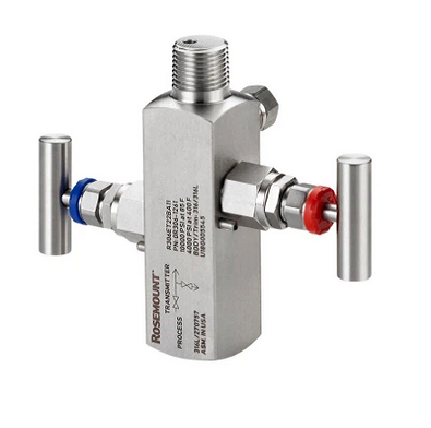 |
Figure 2 below - Rosemount 305 Coplanar™ Style
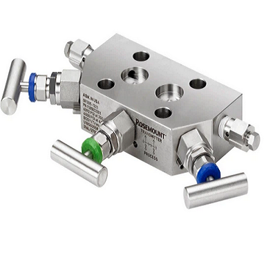 |
Figure 3 below - Rosemount 304 conventional manifold wafer style
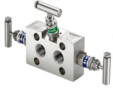 |
Figure 4 below - Rosemount 304 three-valve manifold
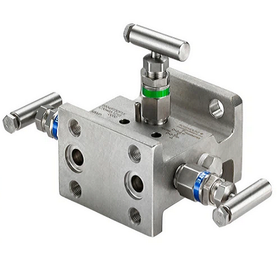 |
Designed and manufactured to maximize the performance of Rosemount transmitters.
performance.
■ Factory assembly saves installation time and money.
■ Available in a variety of forms, materials, and configurations.
Technical specification
| Vibration effects |
When tested in accordance with the field requirements of IEC60770-1: 1999, or when the pipeline vibrates heavily (10-60 Hz 0.21 mm displacement peak amplitude / 60-2000 Hz 3g) Less than ±0.1% URL. |
| Power Supply Effects |
Less than ±0.005% of calibration range for each volt change. |
| Electromagnetic compatibility |
Meets all requirements for industrial environments according to EN61326 and NAMUR NE-21 Maximum deviation during EMC disturbances < 1% of the range. |
| Transient Protection (Option Code T1) |
Tested to IEEE C62.41.2-2002 Class B locations
■ 6 kV peak (0.5 µs - 100 kHz)
■ 3 kA peak (8 x 20 µs)
■ 6 kV peak (1.2 x 50 µs) |
| overpressure limit |
Rosemount 3051TG/TA
■ Range 0: 60 psi (4.14 bar)
■ Range 1: 750 psi (51.71 bar)
Range 1: 750 psi (51.71 bar) ■ Range 2: 1500 psi (103.42 bar)
■ Range 3: 1600 psi (110.32 bar)
■ Range 4: 6000 psi (413.69 bar)
■ Range 5: 15000 psi (1034.21 bar)
■ Range 6: 24000 psi (1654.74 bar) |
| static pressure limit |
Rosemount 3051T Direct Connect
■ Range 0-4: 11016 psi (759.53 bar)
■ Range 5: 26016 psig (1793.74 bar)
■ Range 6: 46092 psi (3177.93 bar) |
| temperature limit |
Ambient Temperature
■ -40 to 185 °F (-40 to 85 °C)
■ With LCD display(1)(2): -40 to 176 °F (-40 to 80 °C)
■ With code BR5: -58 to 185 °F (-50 to 85 °C)
■ Options with code BR6: -76 to 185 °F (-60 to 85 °C) |
| Humidity Limit |
0-100% Relative Humidity |
| Process Connectors |
Rosemount 3051T
■ ½-14 NPT female threads
■ G½ A DIN 16288 male thread (ranges 1-4 only)
■ Model F-250-C autoclave (pressure relief 9/16-18 cap threads; ¼ OD high pressure hose 60° taper angle; range 5-6 transmitters only). |
Dimensional Drawings
|
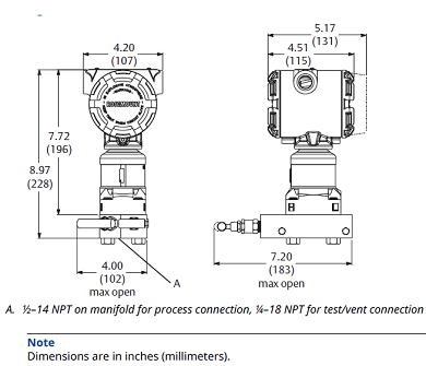
Figure 21: Rosemount 305 Two-Valve Coplanar Style Manifold
|
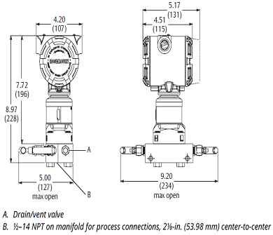 Figure 22: Rosemount 305 Three-Valve Coplanar Style Manifolds Figure 22: Rosemount 305 Three-Valve Coplanar Style Manifolds
|
|
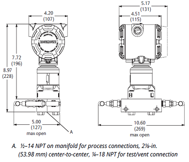
Figure 23: Rosemount 305 Five-Valve Coplanar Style Manifold
|
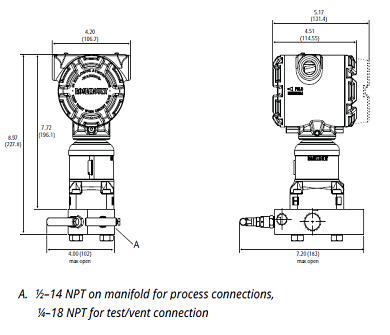
Figure 24: Rosemount 305 Two-Valve Coplanar Style Side Entry Manifold
|
|
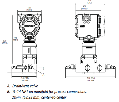
Figure 25: Rosemount 305 Three-Valve Coplanar Style Side Entry Manifold
|
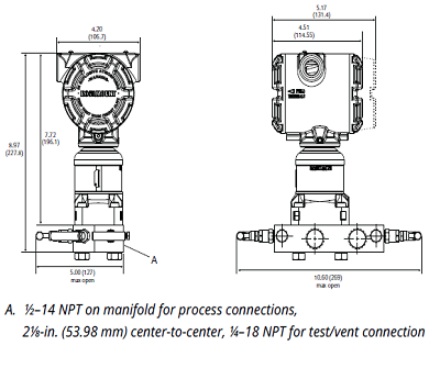
Figure 26: Rosemount 305 Five-Valve Coplanar Style Side Entry Manifold
|
|


