
New Rosemount 3051L2AA0FD31AAS1M5 + 1199MDC05ARTW30DAA5 Differential Pressure Transmitter

Estimated Lead Time : Usually ships in 1-10 working days
Rosemount 1199 Remote Mount Seals are used commonly at the top of the vessel when a DP measurement is required. The capillary that is used is available in three different diameters to optimize time response and reduce temperature effects.
![]() Transmitter Datasheet
Transmitter Datasheet
![]() Diaphragm datasheet
Diaphragm datasheet
- Manufacturer : Rosemount
- Product No. : 3051L2AA0FD31AAS1M5
- Product Type : Flange
- Model : 3051 L - Level Transmitter
- Pressure upper range limit : 2 –250 to 250 inH2O (-621,60 to 621,60 mbar)
- Transmitter output : A - 4–20 mA with Digital Signal Based on HART Protocol
- Process connection size, material, extension length (high side): A0 - Process connection size 3-in./DN 80 - Material 316L SST - Extension length Flush Mount
- Mounting flange size, rating, material (high side): F - 3-in. 316
- Seal fill fluid (high side) : D - Silicone 200
- Low pressure side: 31 - Tuned-System Assembly with Remote Seal
- O-ring: A - Glass-filled PTFE
- Housing material: A - Aluminum / conduit ½–14 NPT
- Seal assemblies: S1 - Assembled to One Rosemount 1199 Seal
- Display Type: M5 - LCD Display for Aluminum Housing (Housing Codes A, B, C, and D only)
- Shipping Weight : 15 Kg
Product parameters
|
Model |
Transmitter type - 3051L2AA0FD31AAS1M5 |
||
| 3051L |
Level Transmitter |
||
|
Pressure range |
|||
|
2 |
–250 to 250 inH2O (-621,60 to 621,60 mbar) |
||
|
3 |
–1000 to 1000 inH2O (-2,48 to 2,48 bar) |
||
|
4 |
–300 to 300 psi (-20,68 to 20,68 bar) |
||
|
Transmitter output |
|||
|
A |
4–20 mA with Digital Signal Based on HART Protocol |
||
|
F |
FOUNDATION fieldbus Protocol |
||
|
W |
PROFIBUS PA Protocol |
||
|
X |
Wireless (requires wireless options and engineered polymer housing) |
||
|
M |
Low-Power 1-5 Vdc with Digital Signal Based on HART Protocol |
||
|
Process connection size, material, extension length (high side) |
|||
|
Code |
Process connection size |
Material |
Extension length |
|
G0 |
2-in./DN 50/A |
316L SST |
Flush Mount Only |
|
H0 |
2-in./DN 50 |
Alloy C-276 |
Flush Mount Only |
|
J0 |
2-in./DN 50 |
Tantalum |
Flush Mount Only |
|
A0 |
3-in./DN 80 |
316L SST |
Flush Mount |
|
A2 |
3-in./DN 80 |
316L SST |
2-in./50 mm |
|
A4 |
3-in./DN 80 |
316L SST |
4-in./100 mm |
|
A6 |
3-in./DN 80 |
316L SST |
6-in./150 mm |
|
|
B0 |
4-in./DN 100 |
316L SST |
Flush Mount |
|
|
B2 |
4-in./DN 100 |
316L SST |
2-in./50 mm |
|
|
B4 |
4-in./DN 100 |
316L SST |
4-in./100 mm |
|
|
B6 |
4-in./DN 100 |
316L SST |
6-in./150 mm |
|
|
C0 |
3-in./DN 80 |
Alloy C-276 |
Flush Mount |
|
|
C2 |
3-in./DN 80 |
Alloy C-276 |
2-in./50 mm |
|
|
C4 |
3-in./DN 80 |
Alloy C-276 |
4-in./100 mm |
|
|
C6 |
3-in./DN 80 |
Alloy C-276 |
6-in./150 mm |
|
|
D0 |
4-in./DN 100 |
Alloy C-276 |
Flush Mount |
|
|
D2 |
4-in./DN 100 |
Alloy C-276 |
2-in./50 mm |
|
|
D4 |
4-in./DN 100 |
Alloy C-276 |
4-in./100 mm |
|
|
D6 |
4-in./DN 100 |
Alloy C-276 |
6-in./150 mm |
|
|
E0 |
3-in./DN 80 |
Tantalum |
Flush Mount Only |
|
|
F0 |
4-in./DN 100 |
Tantalum |
Flush Mount Only |
|
|
Mounting flange size, rating, material (high side) |
||||
|
|
Size |
Rating |
Material |
|
|
M |
2-in. |
ANSI/ASME B16.5 Class 150 |
CS |
|
|
A |
3-in. |
ANSI/ASME B16.5 Class 150 |
CS |
|
|
B |
4-in. |
ANSI/ASME B16.5 Class 150 |
CS |
|
|
N |
2-in. |
ANSI/ASME B16.5 Class 300 |
CS |
|
|
C |
3-in. |
ANSI/ASME B16.5 Class 300 |
CS |
|
|
D |
4-in. |
ANSI/ASME B16.5 Class 300 |
CS |
|
|
P |
2-in. |
ANSI/ASME B16.5 Class 600 |
CS |
|
|
E |
3-in. |
ANSI/ASME B16.5 Class 600 |
CS |
|
|
X |
2-in. |
ANSI/ASME B16.5 Class 150 |
316 SST |
|
|
F |
3-in. |
ANSI/ASME B16.5 Class 150 |
316 SST |
|
|
G |
4-in. |
ANSI/ASME B16.5 Class 150 |
316 SST |
|
|
Y |
2-in. |
ANSI/ASME B16.5 Class 300 |
316 SST |
|
|
H |
3-in. |
ANSI/ASME B16.5 Class 300 |
316 SST |
|
|
J |
4-in. |
ANSI/ASME B16.5 Class 300 |
316 SST |
|
|
Z |
2-in. |
ANSI/ASME B16.5 Class 600 |
316 SST |
|
|
L |
3-in. |
ANSI/ASME B16.5 Class 600 |
316 SST |
|
|
Q |
DN 50 |
PN 10-40 per EN 1092-1 |
CS |
|
|
R |
DN 80 |
PN 40 per EN 1092-1 |
CS |
|
|
S |
DN 100 |
PN 40 per EN 1092-1 |
CS |
|
|
V |
DN 100 |
PN 10/16 per EN 1092-1 |
CS |
|
|
K |
DN 50 |
PN 10-40 per EN 1092-1 |
316 SST |
|
|
T |
DN 80 |
PN 40 per EN 1092-1 |
316 SST |
|
|
U |
DN 100 |
PN 40 per EN 1092-1 |
316 SST |
|
|
Mounting flange size, rating, material (high side) |
||||||
|
|
Size |
Rating |
Material |
|||
|
W |
DN 100 |
PN 10/16 per EN 1092-1 |
316 SST |
|||
|
7 |
4 in. |
ANSI/ASME B16.5 Class 600 |
316 SST |
|||
|
1 |
N/A |
10K per JIS B2238 |
CS |
|||
|
2 |
N/A |
20K per JIS B2238 |
CS |
|||
|
3 |
N/A |
40K per JIS B2238 |
CS |
|||
|
4 |
N/A |
10K per JIS B2238 |
316 SST |
|||
|
5 |
N/A |
20K per JIS B2238 |
316 SST |
|||
|
6 |
N/A |
40K per JIS B2238 |
316 SST |
|||
|
Seal fill fluid (high side) |
Specific gravity |
Temperature limits [ambient temperature of 70° F (21° C)] |
||||
|
D |
Silicone 200 |
0.93 |
-49 to 401 °F (-45 to 205 °C) |
|||
|
F |
Silicone 200 for Vacuum Applications |
0.93 |
For use in vacuum applications below 14.7 psia (1 bar-a), refer to vapor pressure curves in Rosemount DP Level Fill Fluid Specification Technical Note (00840-2100-4016). |
|||
|
L |
Silicone 704 |
1.07 |
32 to 401 °F (0 to 205 °C) |
|||
|
C |
Silicone 704 for Vacuum Applications |
1.07 |
For use in vacuum applications below 14.7 psia (1 bar-a), refer to vapor pressure curves in Rosemount DP Level Fill Fluid Specification Technical Note (00840-2100-4016). |
|||
|
R |
Silicone 705 |
1.09 |
68 to 401 °F (20 to 205 °C) |
|||
|
V |
Silicone 705 for Vacuum Applications |
1.09 |
For use in vacuum applications below 14.7 psia (1 bar-a), refer to vapor pressure curves in Rosemount DP Level Fill Fluid Specification Technical Note (00840-2100-4016). |
|||
|
A |
SYLTHERM™ XLT |
0.85 |
-102 to 293 °F (-75 to 145 °C) |
|||
|
H |
Inert (Halocarbon) |
1.85 |
-49 to 320 °F (-45 to 160 °C) |
|||
|
G |
Glycerine and Water |
1.13 |
5 to 203 °F (-15 to 95 °C) |
|||
|
N |
Neobee® M-20 |
0.92 |
5 to 401 °F (-15 to 205 °C) |
|||
|
P |
Propylene Glycol and Water |
1.02 |
5 to 203 F (-15 to 95 °C) |
|||
|
Low pressure side |
||||||
|
|
Configuration |
Flange adapter |
Diaphragm material |
Sensor fill fluid |
||
|
11 |
Gage |
SST |
316L SST |
Silicone |
||
|
21 |
Differential |
SST |
316L SST |
Silicone |
||
|
22 |
Differential |
SST |
Alloy C-276 |
Silicone |
||
|
2A |
Differential |
SST |
316L SST |
Inert (Halocarbon) |
||
|
2B |
Differential |
SST |
Alloy C-276 |
Inert (Halocarbon) |
||
|
31 |
Tuned-System Assembly with Remote Seal |
None |
316L SST |
Silicone (requires Option Code S1) |
||
|
O-ring |
||
|
A |
Glass-filled PTFE |
|
|
Housing material |
Conduit entry size |
|
|
A |
Aluminum |
½–14 NPT |
|
B |
Aluminum |
M20 × 1.5 |
|
J |
SST |
½–14 NPT |
|
K |
SST |
M20 × 1.5 |
|
P |
Engineered polymer |
No conduit entries |
|
D |
Aluminum |
G½ |
|
M |
SST |
G½ |
|
Wireless transmit rate, operating frequency, and protocol |
|
|
WA3 |
User Configurable Transmit Rate, 2.4GHz WirelessHART |
|
Antenna and SmartPower |
|
|
WP5 |
Internal Antenna, Compatible with Green Power Module (I.S. Power Module Sold Separately) |
HART Revision configuration (requires HART Protocol Output Code A)
|
HR5 |
Configured for HART Revision 5 |
|
HR7 |
Configured for HART Revision 7 |
|
Extended product warranty |
|
|
WR3 |
3-year limited warranty |
|
WR5 |
5-year limited warranty |
|
PlantWeb control functionality |
|
|
A01 |
FOUNDATION fieldbus Control Function Block Suite |
|
PlantWeb diagnostic functionality |
|
|
DA0 |
Power Advisory HART Diagnostic |
|
D01 |
FOUNDATION fieldbus Diagnostics Suite |
|
Seal assemblies |
|
|
S1 |
Assembled to One Rosemount 1199 Seal |
|
Product certifications |
|
|
E8 |
ATEX Flameproof and Dust Certification |
|
I1 |
ATEX Intrinsic Safety and Dust |
|
IA |
ATEX FISCO Intrinsic Safety; for FOUNDATION fieldbus or PROFIBUS PA protocols only |
|
N1 |
ATEX Type n Certification and Dust |
|
K8 |
ATEX Flameproof, Intrinsic Safety, Type n, Dust (combination of E8, I1 and N1) |
|
E4 |
TIIS Flameproof |
|
E5 |
FM Explosion-proof, Dust Ignition-proof |
|
I5 |
FM Intrinsically Safe, Nonincendive |
|
IE |
FM FISCO Intrinsically Safe; for FOUNDATION fieldbus or PROFIBUS PA protocols only |
|
K5 |
FM Explosion-proof, Dust Ignition-Proof, Intrinsically Safe, and Division 2 |
|
Extended product warranty |
|
|
WR3 |
3-year limited warranty |
|
WR5 |
5-year limited warranty |
|
PlantWeb control functionality |
|
|
A01 |
FOUNDATION fieldbus Control Function Block Suite |
|
PlantWeb diagnostic functionality |
|
|
DA0 |
Power Advisory HART Diagnostic |
|
D01 |
FOUNDATION fieldbus Diagnostics Suite |
|
Seal assemblies |
|
|
S1 |
Assembled to One Rosemount 1199 Seal |
|
Product certifications |
|
|
E8 |
ATEX Flameproof and Dust Certification |
|
I1 |
ATEX Intrinsic Safety and Dust |
|
IA |
ATEX FISCO Intrinsic Safety; for FOUNDATION fieldbus or PROFIBUS PA protocols only |
|
N1 |
ATEX Type n Certification and Dust |
|
K8 |
ATEX Flameproof, Intrinsic Safety, Type n, Dust (combination of E8, I1 and N1) |
|
E4 |
TIIS Flameproof |
|
E5 |
FM Explosion-proof, Dust Ignition-proof |
|
I5 |
FM Intrinsically Safe, Nonincendive |
|
IE |
FM FISCO Intrinsically Safe; for FOUNDATION fieldbus or PROFIBUS PA protocols only |
|
K5 |
FM Explosion-proof, Dust Ignition-Proof, Intrinsically Safe, and Division 2 |
| Bolting Material | |
| L4 | Austenitic 316 SST Bolts |
| L5 | ASTM A 193, Grade B7M bolts |
| L6 | Alloy K-500 Bolts |
| L8 | ASTM A 193 Class 2, Grade B8M Bolts |
| Display Type | |
| M4 | LCD Display with Local Operator Interface |
| M5 | LCD Display for Aluminum Housing (Housing Codes A, B, C, and D only) |
| M6 | LCD Display for SST Housing (Housing Codes J, K, L, and M only) |
| Calibration Certification | |
| Q4 | Calibration Certificate |
| QP | Calibration Certificate and tamper evident seal |
| QG | Calibration Certificate and GOST Verification Certificate |
| Material Traceability Certification | |
| Q8 | Material Traceability Certification per EN 10204 3.1 |
|
Toolkit total system performance reports |
|||
|
QZ |
Seal System Performance Calculation Report |
||
|
Conduit electrical connector |
|||
|
GE |
M12, 4-pin, Male Connector (eurofast) |
||
|
GM |
A size Mini, 4-pin, Male Connector (minifast) |
||
|
Configuration buttons |
|||
|
D4 |
Analog Zero and Span |
||
|
DZ |
Digital Zero Trim |
||
|
Transient protection |
|||
|
T1 |
Transient Protection |
||
|
Software configuration |
|||
|
C1 |
Custom Software Configuration (completed CDS 00806-0100-4007 for wired and 00806-0100-4100 for wireless required with order) |
||
|
Low power output |
|||
|
C2 |
0.8-3.2 Vdc Output with Digital Signal Based on HART Protocol (available with Output code M only) |
||
|
Alarm levels |
|||
|
C4 |
NAMUR alarm and saturation levels, high alarm |
||
|
CN |
NAMUR alarm and saturation levels, low alarm |
||
|
CR |
Custom alarm and saturation signal levels, high alarm (requires C1 and Configuration Data Sheet) |
||
|
CS |
Custom alarm and saturation signal levels, low alarm (requires C1 and Configuration Data Sheet) |
||
|
CT |
Rosemount Standard low alarm |
||
|
Conduit plug |
|||
|
DO |
316 SST Conduit Plug |
||
|
Ground screw |
|||
|
V5 |
External Ground Screw Assembly |
||
|
Lower housing flushing connection options |
|||
|
|
Ring material |
Number |
Size (NPT) |
|
F1 |
316 SST |
1 |
1/4-18 NPT |
|
F2 |
316 SST |
2 |
1/4-18 NPT |
|
F3 |
Alloy C-276 |
1 |
1/4-18 NPT |
|
F4 |
Alloy C-276 |
2 |
1/4-18 NPT |
|
F7 |
316 SST |
1 |
1/2-14 NPT |
|
F8 |
316 SST |
2 |
1/2-14 NPT |
|
F9 |
Alloy C-276 |
1 |
1/2-14 NPT |
|
F0 |
Alloy C-276 |
2 |
1/2-14 NPT |
|
Lower housing intermediate gasket material |
|||
|
S0 |
No Gasket for lower housing |
||
|
SY |
Thermo-Tork TN-9000 |
||
|
NACE certificate |
|
|
Q15 |
Certificate of Compliance to NACE MR0175/ISO 15156 for wetted materials |
|
Q25 |
Certificate of Compliance to NACE MR0103 for wetted materials |
|
Typical model number: 3051L2AA0FD31AAS1M5 |
|
See Figure below, which shows an Example how to choose the correct flange
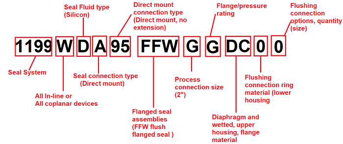
Flange Technical parameters - 1199MDC05RTWA30DAA5
- 1199: Seal system
- M: Connection type, seal type and location - One or two seal system High and low side of transmitter
- D - Seal fill fluid : Silicone 200
- C -Seal connection type/capillary ID: 0.04-in. (1.092 mm) ID
- 05 - Capillary length: 5.0 ft. (1.5 m)
- RTW - RTW Extended Flanged Seal
- A - Industry standards: ASME B1.20.1
- 3 - Process connection size: ½–14 NPT
- 0 - Pressure rating: 2500psi
- DA - Diaphragm, upper housing, flange material: 316L SST
- A - Flushing connection ring material (lower housing): 316L SST
- 5 - Flushing connections (connection size): None
Transmitter Dimension
|
|
High side flange Connection |
|
low side flange connection |
low side flange connection |


If you need help do not hesitate to fill out the form with all the details on the main page

+(39) 347 051 5328
Italy - Kazakhstan


09.00am to 18.00pm
About
We offer the best and economical solutions, backed by 27+ years of experience and international standards knowledge, echnological changes, and industrial systems.
Our Services
Marketing Materials


Marketing Materials1


