|
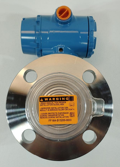
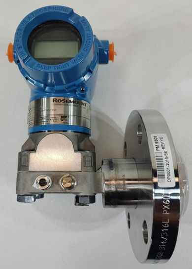
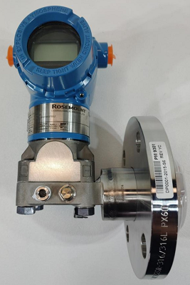
Rosemount DP Transmitter 3051L2AH0XD11AAE5M5F9SJ Level Transmitter
Estimated Lead Time : Usually ships in 1-10 working days
 Transmitter Datasheet Transmitter Datasheet
- Manufacturer : Rosemount
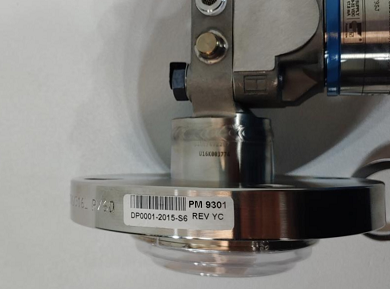
- Product No. : 3051L2AH0XD11AAE5M5F9SJ
- Model : 3051 L - Level transmitter
- Pressure range : 2 - –250 to 250 inH2O (-621,60 to 621,60 mbar
- Transmitter output : A - 4–20 mA with Digital Signal Based on HART Protocol
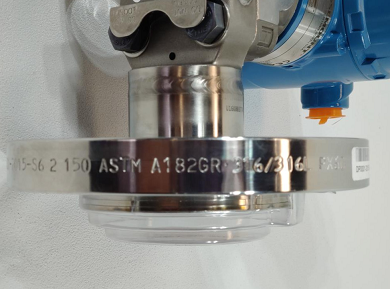
- Process connection size, material, extension length (high side): H0 - 2-in./DN 50, Alloy C-276, Flush mount only
- Mounting flange size, rating, material (high side): X - 2-in. AcSME B16.5 Class 150
- Sensor fill fluid : D - Silicone
- Low pressure side: 11 - Gauge, SST 316L, SST
- O-ring: A - Glass-filled PTFE
- Housing material: A - Aluminum / ½–14 NPT
- Product certifications: E5 - USA Explosion-proof, Dust Ignition-proof
- Display and interface options: M5 -LCD Display
- Lower housing flushing connection options: F9 - Alloy C-276 , 1 ½–14 NPT
|
Model
|
Transmitter type 3051L2AH0XD11AAE5M5F9SJ
|
| 3051L |
Level Transmitter |
|
Pressure range
|
|
2
|
–250 to 250 inH2O (-621,60 to 621,60 mbar)
|
|
3
|
–1000 to 1000 inH2O (-2,48 to 2,48 bar)
|
|
4
|
–300 to 300 psi (-20,68 to 20,68 bar)
|
|
Transmitter output
|
|
A
|
4–20 mA with Digital Signal Based on HART Protocol
|
|
F
|
FOUNDATION fieldbus Protocol
|
|
W
|
PROFIBUS PA Protocol
|
|
X
|
Wireless (requires wireless options and engineered polymer housing)
|
|
M
|
Low-Power 1-5 Vdc with Digital Signal Based on HART Protocol
|
|
Process connection size, material, extension length (high side)
|
|
Code
|
Process connection size
|
Material
|
Extension length
|
|
G0
|
2-in./DN 50/A
|
316L SST
|
Flush Mount Only
|
|
H0
|
2-in./DN 50
|
Alloy C-276
|
Flush Mount Only
|
|
J0
|
2-in./DN 50
|
Tantalum
|
Flush Mount Only
|
|
A0
|
3-in./DN 80
|
316L SST
|
Flush Mount
|
|
A2
|
3-in./DN 80
|
316L SST
|
2-in./50 mm
|
|
A4
|
3-in./DN 80
|
316L SST
|
4-in./100 mm
|
|
A6
|
3-in./DN 80
|
316L SST
|
6-in./150 mm
|
|
B0
|
4-in./DN 100
|
316L SST
|
Flush Mount
|
|
B2
|
4-in./DN 100
|
316L SST
|
2-in./50 mm
|
|
B4
|
4-in./DN 100
|
316L SST
|
4-in./100 mm
|
|
B6
|
4-in./DN 100
|
316L SST
|
6-in./150 mm
|
|
C0
|
3-in./DN 80
|
Alloy C-276
|
Flush Mount
|
|
C2
|
3-in./DN 80
|
Alloy C-276
|
2-in./50 mm
|
|
C4
|
3-in./DN 80
|
Alloy C-276
|
4-in./100 mm
|
|
C6
|
3-in./DN 80
|
Alloy C-276
|
6-in./150 mm
|
|
D0
|
4-in./DN 100
|
Alloy C-276
|
Flush Mount
|
|
D2
|
4-in./DN 100
|
Alloy C-276
|
2-in./50 mm
|
|
D4
|
4-in./DN 100
|
Alloy C-276
|
4-in./100 mm
|
|
D6
|
4-in./DN 100
|
Alloy C-276
|
6-in./150 mm
|
|
E0
|
3-in./DN 80
|
Tantalum
|
Flush Mount Only
|
|
F0
|
4-in./DN 100
|
Tantalum
|
Flush Mount Only
|
|
Mounting flange size, rating, material (high side)
|
|
|
Size
|
Rating
|
Material
|
|
M
|
2-in.
|
ANSI/ASME B16.5 Class 150
|
CS
|
|
A
|
3-in.
|
ANSI/ASME B16.5 Class 150
|
CS
|
|
B
|
4-in.
|
ANSI/ASME B16.5 Class 150
|
CS
|
|
N
|
2-in.
|
ANSI/ASME B16.5 Class 300
|
CS
|
|
C
|
3-in.
|
ANSI/ASME B16.5 Class 300
|
CS
|
|
D
|
4-in.
|
ANSI/ASME B16.5 Class 300
|
CS
|
|
P
|
2-in.
|
ANSI/ASME B16.5 Class 600
|
CS
|
|
E
|
3-in.
|
ANSI/ASME B16.5 Class 600
|
CS
|
|
X
|
2-in.
|
ANSI/ASME B16.5 Class 150
|
316 SST
|
|
F
|
3-in.
|
ANSI/ASME B16.5 Class 150
|
316 SST
|
|
G
|
4-in.
|
ANSI/ASME B16.5 Class 150
|
316 SST
|
|
Y
|
2-in.
|
ANSI/ASME B16.5 Class 300
|
316 SST
|
|
H
|
3-in.
|
ANSI/ASME B16.5 Class 300
|
316 SST
|
|
J
|
4-in.
|
ANSI/ASME B16.5 Class 300
|
316 SST
|
|
Z
|
2-in.
|
ANSI/ASME B16.5 Class 600
|
316 SST
|
|
L
|
3-in.
|
ANSI/ASME B16.5 Class 600
|
316 SST
|
|
Q
|
DN 50
|
PN 10-40 per EN 1092-1
|
CS
|
|
R
|
DN 80
|
PN 40 per EN 1092-1
|
CS
|
|
S
|
DN 100
|
PN 40 per EN 1092-1
|
CS
|
|
V
|
DN 100
|
PN 10/16 per EN 1092-1
|
CS
|
|
K
|
DN 50
|
PN 10-40 per EN 1092-1
|
316 SST
|
|
T
|
DN 80
|
PN 40 per EN 1092-1
|
316 SST
|
|
U
|
DN 100
|
PN 40 per EN 1092-1
|
316 SST
|
|
Mounting flange size, rating, material (high side)
|
|
|
Size
|
Rating
|
Material
|
|
W
|
DN 100
|
PN 10/16 per EN 1092-1
|
316 SST
|
|
7
|
4 in.
|
ANSI/ASME B16.5 Class 600
|
316 SST
|
|
1
|
N/A
|
10K per JIS B2238
|
CS
|
|
2
|
N/A
|
20K per JIS B2238
|
CS
|
|
3
|
N/A
|
40K per JIS B2238
|
CS
|
|
4
|
N/A
|
10K per JIS B2238
|
316 SST
|
|
5
|
N/A
|
20K per JIS B2238
|
316 SST
|
|
6
|
N/A
|
40K per JIS B2238
|
316 SST
|
|
Seal fill fluid (high side)
|
Specific gravity
|
Temperature limits [ambient temperature of 70° F (21° C)]
|
|
D
|
Silicone 200
|
0.93
|
-49 to 401 °F (-45 to 205 °C)
|
|
F
|
Silicone 200 for Vacuum Applications
|
0.93
|
For use in vacuum applications below 14.7 psia (1 bar-a), refer to vapor pressure curves in Rosemount DP Level Fill Fluid Specification Technical Note (00840-2100-4016).
|
|
L
|
Silicone 704
|
1.07
|
32 to 401 °F (0 to 205 °C)
|
|
C
|
Silicone 704 for Vacuum Applications
|
1.07
|
For use in vacuum applications below 14.7 psia (1 bar-a), refer to vapor pressure curves in Rosemount DP Level Fill Fluid Specification Technical Note (00840-2100-4016).
|
|
R
|
Silicone 705
|
1.09
|
68 to 401 °F (20 to 205 °C)
|
|
V
|
Silicone 705 for Vacuum Applications
|
1.09
|
For use in vacuum applications below 14.7 psia (1 bar-a), refer to vapor pressure curves in Rosemount DP Level Fill Fluid Specification Technical Note (00840-2100-4016).
|
|
A
|
SYLTHERM™ XLT
|
0.85
|
-102 to 293 °F (-75 to 145 °C)
|
|
H
|
Inert (Halocarbon)
|
1.85
|
-49 to 320 °F (-45 to 160 °C)
|
|
G
|
Glycerine and Water
|
1.13
|
5 to 203 °F (-15 to 95 °C)
|
|
N
|
Neobee® M-20
|
0.92
|
5 to 401 °F (-15 to 205 °C)
|
|
P
|
Propylene Glycol and Water
|
1.02
|
5 to 203 F (-15 to 95 °C)
|
|
Low pressure side
|
|
|
Configuration
|
Flange adapter
|
Diaphragm material
|
Sensor fill fluid
|
|
11
|
Gage
|
SST
|
316L SST
|
Silicone
|
|
21
|
Differential
|
SST
|
316L SST
|
Silicone
|
|
22
|
Differential
|
SST
|
Alloy C-276
|
Silicone
|
|
2A
|
Differential
|
SST
|
316L SST
|
Inert (Halocarbon)
|
|
2B
|
Differential
|
SST
|
Alloy C-276
|
Inert (Halocarbon)
|
|
31
|
Tuned-System Assembly with Remote Seal
|
None
|
316L SST
|
Silicone
(requires Option Code S1)
|
|
O-ring
|
|
A
|
Glass-filled PTFE
|
|
Housing material
|
Conduit entry size
|
|
A
|
Aluminum
|
½–14 NPT
|
|
B
|
Aluminum
|
M20 × 1.5
|
|
J
|
SST
|
½–14 NPT
|
|
K
|
SST
|
M20 × 1.5
|
|
P
|
Engineered polymer
|
No conduit entries
|
|
D
|
Aluminum
|
G½
|
|
M
|
SST
|
G½
|
|
Wireless transmit rate, operating frequency, and protocol
|
|
WA3
|
User Configurable Transmit Rate, 2.4GHz WirelessHART
|
|
Antenna and SmartPower
|
|
WP5
|
Internal Antenna, Compatible with Green Power Module (I.S. Power Module Sold Separately)
|
HART Revision configuration (requires HART Protocol Output Code A)
|
HR5
|
Configured for HART Revision 5
|
|
HR7
|
Configured for HART Revision 7
|
|
Extended product warranty
|
|
WR3
|
3-year limited warranty
|
|
WR5
|
5-year limited warranty
|
|
PlantWeb control functionality
|
|
A01
|
FOUNDATION fieldbus Control Function Block Suite
|
|
PlantWeb diagnostic functionality
|
|
DA0
|
Power Advisory HART Diagnostic
|
|
D01
|
FOUNDATION fieldbus Diagnostics Suite
|
|
Seal assemblies
|
|
S1
|
Assembled to One Rosemount 1199 Seal
|
|
Product certifications
|
|
E8
|
ATEX Flameproof and Dust Certification
|
|
I1
|
ATEX Intrinsic Safety and Dust
|
|
IA
|
ATEX FISCO Intrinsic Safety; for FOUNDATION fieldbus or PROFIBUS PA protocols only
|
|
N1
|
ATEX Type n Certification and Dust
|
|
K8
|
ATEX Flameproof, Intrinsic Safety, Type n, Dust (combination of E8, I1 and N1)
|
|
E4
|
TIIS Flameproof
|
|
E5
|
FM Explosion-proof, Dust Ignition-proof
|
|
I5
|
FM Intrinsically Safe, Nonincendive
|
|
IE
|
FM FISCO Intrinsically Safe; for FOUNDATION fieldbus or PROFIBUS PA protocols only
|
|
K5
|
FM Explosion-proof, Dust Ignition-Proof, Intrinsically Safe, and Division 2
|
|
C6
|
CSA Explosion-proof, Dust Ignition-proof, Intrinsically Safe, and Division 2
|
|
I6
|
CSA Intrinsic Safety
|
|
K6
|
CSA and ATEX Explosion-proof, Intrinsically Safe, and Division 2 (combination of C6, E8, and I1)
|
|
E7
|
IECEx Flameproof, Dust Ignition-proof
|
|
I7
|
IECEx Intrinsic Safety
|
|
N7
|
IECEx Type n Certification
|
|
K7
|
IECEx Flameproof, Dust Ignition-proof, Intrinsic Safety, and Type n (combination of I7, N7 and E7)
|
|
E2
|
INMETRO Flameproof
|
|
I2
|
INMETRO Intrinsic Safety
|
|
IB
|
INMETRO FISCO intrinsically safe; for FOUNDATION fieldbus or PROFIBUS PA protocols only
|
|
K2
|
INMETRO Flameproof, Intrinsic Safety
|
|
E3
|
China Flameproof
|
|
I3
|
China Intrinsic Safety
|
|
N3
|
China Type n
|
|
EM
|
Technical Regulations Customs Union (EAC) Flameproof
|
|
IM
|
Technical Regulations Customs Union (EAC) Intrinsic Safety
|
|
KM
|
Technical Regulations Customs Union (EAC) Flameproof and Intrinsic Safety
|
|
KB
|
FM and CSA Explosion-proof, Dust Ignition Proof, Intrinsically Safe, and Division 2 (combination of K5 and C6)
|
|
KD
|
FM, CSA, and ATEX Explosion-proof, Intrinsically Safe (combination of K5, C6, I1, and E8)
|
|
Shipboard approvals
|
|
SBS
|
American Bureau of Shipping
|
|
SBV
|
Bureau Veritas (BV)
|
|
SDN
|
Det Norske Veritas
|
|
SLL
|
Lloyds Register (LR)
|
|
Bolting material
|
|
L4
|
Austenitic 316 SST Bolts
|
|
L5
|
ASTM A 193, Grade B7M bolts
|
|
L6
|
Alloy K-500 Bolts
|
|
L8
|
ASTM A 193 Class 2, Grade B8M Bolts
|
|
Display and interface options
|
|
M4
|
LCD Display with Local Operator Interface
|
|
M5
|
LCD Display
|
|
Calibration certification
|
|
Q4
|
Calibration Certificate
|
|
QP
|
Calibration Certificate and tamper evident seal
|
|
QG
|
Calibration Certificate and GOST Verification Certificate
|
|
Material traceability certification
|
|
Q8
|
Material Traceability Certification per EN 10204 3.1
|
|
Quality certification for safety
|
|
QS
|
Prior-use certificate of FMEDA data
|
|
QT
|
Safety certified to IEC 61508 with certificate of FMEDA
|
|
Toolkit total system performance reports
|
|
QZ
|
Seal System Performance Calculation Report
|
|
Conduit electrical connector
|
|
GE
|
M12, 4-pin, Male Connector (eurofast)
|
|
GM
|
A size Mini, 4-pin, Male Connector (minifast)
|
|
Configuration buttons
|
|
D4
|
Analog Zero and Span
|
|
DZ
|
Digital Zero Trim
|
|
Transient protection
|
|
T1
|
Transient Protection
|
|
Software configuration
|
|
C1
|
Custom Software Configuration (completed CDS 00806-0100-4007 for wired and 00806-0100-4100 for wireless required with order)
|
|
Low power output
|
|
C2
|
0.8-3.2 Vdc Output with Digital Signal Based on HART Protocol (available with Output code M only)
|
|
Alarm levels
|
|
C4
|
NAMUR alarm and saturation levels, high alarm
|
|
CN
|
NAMUR alarm and saturation levels, low alarm
|
|
CR
|
Custom alarm and saturation signal levels, high alarm (requires C1 and Configuration Data Sheet)
|
|
CS
|
Custom alarm and saturation signal levels, low alarm (requires C1 and Configuration Data Sheet)
|
|
CT
|
Rosemount Standard low alarm
|
|
Conduit plug
|
|
DO
|
316 SST Conduit Plug
|
|
Ground screw
|
|
V5
|
External Ground Screw Assembly
|
|
Lower housing flushing connection options
|
|
|
Ring material
|
Number
|
Size (NPT)
|
|
F1
|
316 SST
|
1
|
1/4-18 NPT
|
|
F2
|
316 SST
|
2
|
1/4-18 NPT
|
|
F3
|
Alloy C-276
|
1
|
1/4-18 NPT
|
|
F4
|
Alloy C-276
|
2
|
1/4-18 NPT
|
|
F7
|
316 SST
|
1
|
1/2-14 NPT
|
|
F8
|
316 SST
|
2
|
1/2-14 NPT
|
|
F9
|
Alloy C-276
|
1
|
1/2-14 NPT
|
|
F0
|
Alloy C-276
|
2
|
1/2-14 NPT
|
|
Lower housing intermediate gasket material
|
|
S0
|
No Gasket for lower housing
|
|
SY
|
Thermo-Tork TN-9000
|
|
NACE certificate
|
|
Q15
|
Certificate of Compliance to NACE MR0175/ISO 15156 for wetted materials
|
|
Q25
|
Certificate of Compliance to NACE MR0103 for wetted materials
|
|
Typical model number: 3051L2AH0XD11AAE5M5F9SJ
|
Dimensional Drawing
Dimensional Drawing
Note: There are several models, to choose the correct one for your aplication, please fill the form below
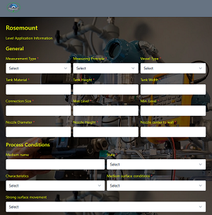
If you need help do not hesitate to fill out the form with all the details on the main page
|