|
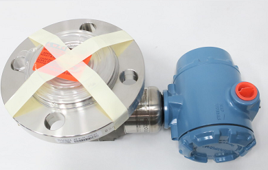
Rosemount 3051SAL1CG4AA1A1020DFFG1DBB3E5M5Q4 Level Transmitter
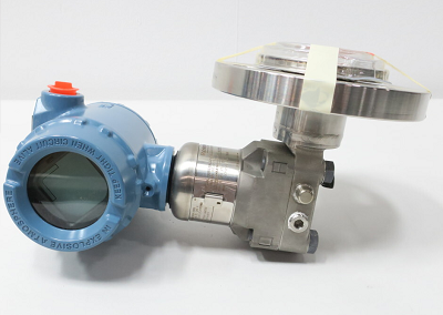
The Rosemount 3051SAL Liquid Level Transmitter System is a flexible, 2-wire 4-20mA HART architecture that calculates differential pressure (DP) electronically using two pressure sensors that are linked together with a non-proprietary electrical wire.
Ideal applications for the 3051SAL ERS System include tall vessels and distillation columns that have traditionally required long lengths of capillary or impulse piping. When used in these types of applications, the 3051S ERS System can deliver:
- More accurate and repeatable DP measurements
- Faster time response
- Simplified installations
- Reduced maintenance
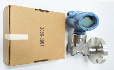
Estimated Lead Time : Usually ships in 1-10 working days
 Transmitter Datasheet Transmitter Datasheet
- Manufacturer : Rosemount
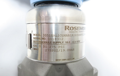
- Product No. : 3051SAL1CG4AA1A1020DFFG1DBB3E5M5Q4
- Model : 3051SAL - Level transmitter
- Performance class: 1 - Ultra: 0.055% span accuracy, 150:1 rangedown, 15-year limited warranty
- Configuration type: C - Liquid level transmitter
- Pressure module type: G - Coplanar - sensor type Gauge
- Pressure range: 4A - –14.2 to 300 psig (–0.97 to 20.68 bar)
- Transmitter output : A - 4–20 mA with Digital Signal Based on HART Protocol
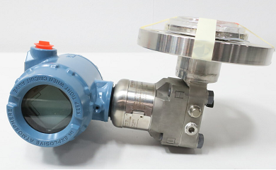
- Housing style: 1A - Plantweb™ housing - Aluminum - Conduit entry size ½–14 NPT
- Seal system type: 1 - Direct mount single seal system
- High side connection type (select based on seal system type chosen): 0 - No extension
- Low side connection type or capillary I.D.: 2 - Assemble to one Rosemount remote seal
- Capillary length: 0 - No capillary (required for direct mount single seal system)
- Seal fill fluid: D - Silicone 200
- model components (flange): FFG - 2-in. (type flange - see second PDF)
- Flange/pressure rating: 1 - ASME B16.5 Class 150
- Materials of construction: DB - Alloy C-276, seam-welded
- Flushing connection ring (lower housing): B - Alloy C-276
- Flushing connection quantity and size: 3 - Two ¼–18 NPT flushing connections
- Product certifications: E5 - USA Explosion-proof, Dust Ignition-proof
- Display type: M5 -LCD Display
- Calibration certification: Q4 - Calibration certificate
|
Code
|
Transmitter type 3051SAL1CG4AA1A1020DFFG1DBB3E5M5Q4
|
|
3051SAL
|
Scalable level transmitter
|
Performance class
|
Code
|
Description
|
|
1
|
Ultra: 0.055% span accuracy, 150:1 rangedown, 15-year limited warranty
|
|
2
|
Classic: 0.065% span accuracy, 150:1 rangedown
|
Configuration type
|
Code
|
Description
|
|
C
|
Liquid level transmitter
|
Pressure module type
|
Code
|
Module type
|
Sensor type
|
|
D
|
Coplanar
|
Differential
|
|
G
|
Coplanar
|
Gauge
|
|
T
|
In-line
|
Gauge
|
Pressure range
|
Code
|
Coplanar DP
|
Coplanar Gauge
|
In-line Gauge
|
In-line Absolute
|
Coplanar Absolute
|
|
1A
|
N/A
|
N/A
|
–14.7 to 30 psig
(–1.01 to 2.06 bar)
|
0 to 30 psia
(0 to 2.06 bar)
|
0 to 30 psia
(0 to 2.06 bar)
|
|
2A
|
–250 to 250 inH2O
(–621.60 to 621.60
mbar)
|
–250 to 250 inH2O
(–621.60 to 621.60
mbar)
|
–14.7 to 150 psig
(–1.01 to 10.34 bar)
|
0 to 150 psia
(0 to 10.34 bar)
|
0 to 150 psia
(0 to 10.34 bar)
|
|
Code
|
Coplanar DP
|
Coplanar Gauge
|
In-line Gauge
|
In-line Absolute
|
Coplanar Absolute
|
|
3A
|
–1000 to 1000 inH2O
(–2.48 to 2.48 bar)
|
–393 to 1000 inH2O
(–0.97 to 2.48 bar)
|
–14.7 to 800 psig
(–1.01 to 55.15 bar)
|
0 to 800 psia
(0 to 55.15 bar)
|
0 to 800 psia
(0 to 55.15 bar)
|
|
4A
|
–300 to 300 psi
(–20.68 to 20.68 bar)
|
–14.2 to 300 psig
(–0.97 to 20.68 bar)
|
–14.7 to 4000 psig
(–1.01 to 275.79 bar)
|
0 to 4000 psia
(0 to 275.79 bar)
|
0 to 4000 psia
(0 to 275.79 bar)
|
|
5A
|
–2000 to 2000 psi
(–137.89 to 137.89 bar)
|
–14.2 to 2000 psig
(–0.97 to 137.89 bar)
|
–14.7 to 10000 psig
(–1.01 to 689.47 bar)
|
0 to 10000 psia
(0 to 689.47 bar)
|
N/A
|
Transmitter output
|
Code
|
Description
|
|
A
|
4–20 mA with digital signal based on HART® protocol
|
|
F(1)
|
FOUNDATION™ Fieldbus protocol
|
|
X(2)
|
Wireless (requires wireless options and wireless Plantweb™ housing)
|
Housing style
|
Code
|
Description
|
Material
|
Conduit entry size
|
|
Housings for ERS primary - configuration type code P
|
|
1A
|
Plantweb™ housing
|
Aluminum
|
½–14 NPT
|
|
1B
|
Plantweb housing
|
Aluminum
|
M20 x 1.5 (CM 20)
|
|
1J
|
Plantweb housing
|
SST
|
½–14 NPT
|
|
1K
|
Plantweb housing
|
SST
|
M20 x 1.5 (CM 20)
|
|
2E
|
Junction box with remote display output
|
Aluminum
|
½–14 NPT
|
|
2F
|
Junction box with remote display output
|
Aluminum
|
M20 x 1.5 (CM 20)
|
|
2M
|
Junction box with remote display output
|
SST
|
½–14 NPT
|
|
1C
|
Plantweb housing
|
Aluminum
|
G½
|
|
1L
|
Plantweb housing
|
SST
|
G½
|
|
2G
|
Junction box with remote display output
|
Aluminum
|
G½
|
|
Housings for ERS secondary - configuration type code S
|
|
2A
|
Junction box
|
Aluminum
|
½–14 NPT
|
|
2B
|
Junction box
|
Aluminum
|
M20 x 1.5 (CM 20)
|
|
2J
|
Junction box
|
SST
|
½–14 NPT
|
|
2C
|
Junction box
|
Aluminum
|
G½
|
Seal system type
|
Code
|
Coplanar pressure module type
|
In-line pressure module type
|
|
1
|
Direct mount single seal system
|
Welded-repairable
|
Direct mount single seal system
|
All welded
|
|
Code
|
Coplanar pressure module type
|
In-line pressure module type
|
|
2
|
Direct mount single seal system
|
All welded
|
N/A
|
N/A
|
|
3
|
Tuned-system assembly - one direct mount and one remote mount seal with capillary
|
Welded-repairable
|
N/A
|
N/A
|
|
4
|
Tuned-system assembly - one direct mount and one remote mount seal with capillary
|
All welded
|
N/A
|
N/A
|
|
5
|
Balanced system - two remote mount seals with equal lengths of capillary
|
Welded-repairable
|
N/A
|
N/A
|
|
B
|
Balanced system - two remote mount seals with equal lengths of capillary
|
All welded
|
N/A
|
N/A
|
|
7
|
Remote mount single seal system with capillary - 316L low side transmitter isolator
|
Welded-repairable
|
Remote mount single seal system with capillary
|
All welded
|
|
8
|
Remote mount single seal system with capillary (legacy design)
|
316L low side transmitter isolator - All welded
|
N/A
|
N/A
|
|
C
|
Remote mount single seal system with capillary - 316L low side transmitter isolator
|
All welded
|
N/A
|
N/A
|
|
9
|
Remote mount single seal system with capillary - Alloy C-276 low side transmitter isolator
|
Welded-repairable
|
N/A
|
N/A
|
|
A
|
Remote mount single seal system with capillary (legacy design)
|
Alloy C-276 low side transmitter isolator - All welded
|
N/A
|
N/A
|
|
D
|
Remote mount single seal system with capillary - Alloy C-276 low side transmitter isolator
|
All welded
|
N/A
|
N/A
|
High side connection type (select based on seal system type chosen)
|
Code
|
Single seal system
|
Dual seal system
|
|
|
Direct mount
|
Remote mount with capillary
|
Tuned-system assembly
|
Balanced system
|
|
|
Coplanar
|
In-line
|
Coplanar
|
In-line
|
Coplanar
|
Coplanar
|
|
0
|
No extension
|
Standard
|
Standard
|
No extension/Standard
|
Standard
|
|
2
|
2-in. (50 mm) extension
|
N/A
|
N/A
|
N/A
|
2-in. (50 mm) extension
|
|
|
4
|
4-in. (100 mm) extension
|
4-in. (100
mm) extension(1)
|
N/A
|
N/A
|
4-in. (100 mm) extension
|
N/A
|
|
5
|
N/A
|
Thermal optimizer
|
N/A
|
N/A
|
N/A
|
N/A
|
|
6(2)
|
Thermal Range Expander - Silicone 200 secondary fill
|
Thermal Range Expander - Silicone 200 secondary fill fluid single capillary
|
Thermal Range Expander - Silicone 200 secondary fill with low side capillary
|
|
7(2)
|
Thermal Range Expander - SYLTHERM XLT secondary fill fluid
|
Thermal Range Expander - SYLTHERM XLT secondary fill fluid single capillary
|
Thermal Range Expander - SYLTHERM XLT secondary fill with low side capillary
|
|
Code
|
Single seal system
|
Dual seal system
|
|
|
Direct mount
|
Remote mount with capillary
|
Tuned-system assembly
|
Balanced system
|
|
8(2)
|
Thermal Range Expander - Tri-Therm 300 secondary fill fluid
|
Tri-Therm 300 secondary fill fluid single capillary
|
Tri-Therm 300 secondary fill fluid with low side capillary
|
Low side connection type or capillary I.D.
|
Code
|
Material for low side reference connection
|
Capillary I.D.
|
|
|
Direct mount
|
Remote mount with capillary
|
Tuned- system assembly
|
Balanced system
|
|
|
Coplanar
|
In-line
|
Coplanar or In-line
|
Coplanar
|
Coplanar
|
|
0
|
N/A
|
No reference connection
|
N/A
|
N/A
|
N/A
|
|
1(1)(2)
|
Assemble to one Rosemount remote seal
|
N/A
|
N/A
|
N/A
|
N/A
|
|
2
|
316L SST isolator and SST transmitter flange
|
N/A
|
N/A
|
N/A
|
N/A
|
|
3
|
Alloy C-276 isolator and SST transmitter flange
|
N/A
|
N/A
|
N/A
|
N/A
|
|
B
|
N/A
|
N/A
|
0.03-in. (0.711 mm) ID
capillary
|
0.03-in.
(0.711 mm)
ID capillary
|
0.03-in. (0.711 mm) ID
capillary
|
|
C
|
N/A
|
N/A
|
0.04-in. (1.092 mm) ID
capillary
|
0.04-in.
(1.092 mm)
ID capillary
|
0.04-in. (1.092 mm) ID
capillary
|
|
D
|
N/A
|
N/A
|
0.075-in. (1.905 mm) ID
capillary
|
0.075-in.
(1.905 mm)
ID capillary
|
0.075-in. (1.905 mm) ID
capillary
|
|
E(3)
|
N/A
|
N/A
|
0.03-in. (0.711 mm) ID
capillary, PVC coated with closed end
|
0.03-in.
(0.711 mm)
ID capillary, PVC coated with closed end
|
0.03-in. (0.711 mm) ID
capillary, PVC coated with closed end
|
|
F
|
N/A
|
N/A
|
0.04-in. (1.092 mm) ID
capillary, PVC coated with closed end
|
0.04-in.
(1.092 mm)
ID capillary, PVC coated with closed end
|
0.04-in. (1.092 mm) ID
capillary, PVC coated with closed end
|
|
G
|
N/A
|
N/A
|
0.075-in. (1.905 mm) ID
capillary, PVC coated with closed end
|
0.075-in.
(1.905 mm)
ID capillary, PVC coated with closed end
|
0.075-in. (1.905 mm) ID
capillary, PVC coated with closed end
|
Capillary length
|
Code
|
Description
|
|
0
|
No capillary (required for direct mount single seal system)
|
|
A
|
1 ft. (0.3 m)
|
|
B
|
5 ft. (1.5 m)
|
|
C
|
10 ft. (3.0 m)
|
|
D
|
15 ft. (4.5 m)
|
|
E
|
20 ft. (6.1 m)
|
|
F
|
25 ft. (7.6 m)
|
|
G
|
30 ft. (9.1 m)
|
|
H
|
35 ft. (10.7 m)
|
|
J
|
40 ft. (12.2 m)
|
|
K
|
45 ft. (13.7 m)
|
|
L
|
50 ft. (15.2 m)
|
|
M
|
1.6 ft. (0.5 m)
|
|
N
|
3.3 ft. (1.0 m)
|
|
P
|
4.9 ft. (1.5 m)
|
|
R
|
6.6 ft. (2.0 m)
|
|
T
|
8.2 ft. (2.5 m)
|
|
U
|
9.8 ft. (3.0 m)
|
|
V
|
11.5 ft. (3.5 m)
|
|
W
|
13.1 ft. (4.0 m)
|
|
Y
|
16.4 ft. (5.0 m)
|
|
Z
|
19.7 ft. (6.0 m)
|
|
1
|
23 ft. (7.0 m)
|
|
2
|
26.2 ft. (8.0 m)
|
|
3
|
29.5 ft. (9.0 m)
|
|
4
|
32.8 ft. (10.0 m)
|
|
5
|
36.1 ft. (11.0 m)
|
|
6
|
39.4 ft. (12.0 m)
|
|
7
|
42.6 ft. (13.0 m)
|
|
8
|
45.9 ft. (14.0 m)
|
|
9
|
49.2 ft. (15.0 m)
|
Seal fill fluid
|
Code
|
Description
|
Specific gravity at 77 °F (25 °C)
|
Temperature limits(1)(2)
|
|
No extension
|
2-in. (50 mm) extension
|
4-in. (100 mm) extension
|
Thermal Range Expander(3)
|
|
D
|
Silicone 200
|
0.934
|
–49 to 401 °F (–45 to 205 °C)
|
N/A
|
|
F
|
Silicone 200 for vacuum applications
|
0.934
|
For use in vacuum applications below 14.7 psia (1 bar-a), refer to vapor pressure curves in Rosemount DP Level Fill Fluid Specification Technical Note.
|
|
J(4)
|
Tri-Therm 300
|
0.795
|
–40 to 401 °F
(–40 to 205 °C)
|
–40 to 464 °F
(–40 to 240 °C)
|
–40 to 572 °F
(–40 to 300 °C)
|
N/A
|
|
Q(4)
|
Tri-Therm 300 for vacuum applications
|
0.795
|
For use in vacuum applications below 14.7 psia (1 bar-a), refer to vapor pressure curves in Rosemount DP Level Fill Fluid Specification Technical Note.
|
|
L
|
Silicone 704
|
1.07
|
32 to 401 °F
(0 to 205 °C)
|
32 to 464 °F
(0 to 240 °C)
|
32 to 572 °F
(0 to 300 °C)
|
Up to 599 °F (315 °C)
|
|
C
|
Silicone 704 for vacuum applications
|
1.07
|
For use in vacuum applications below 14.7 psia (1 bar-a), refer to vapor pressure curves in Rosemount DP Level Fill Fluid Specification Technical Note.
|
|
R
|
Silicone 705
|
1.09
|
68 to 401 °F
(20 to 205 °C)
|
68 to 464 °F
(20 to 240 °C)
|
68 to 572 °F
(20 to 300 °C)
|
Up to 698 °F (370 °C)
|
|
V
|
Silicone 705 for vacuum applications
|
1.09
|
For use in vacuum applications below 14.7 psia (1 bar-a), refer to vapor pressure curves in Rosemount DP Level Fill Fluid Specification Technical Note.
|
|
A(5)
|
SYLTHERM™ XLT
|
0.85
|
–157 to 293 °F (–105 to 145 °C)
|
N/A
|
|
H(5)
|
Inert (Halocarbon)
|
1.85
|
–49 to 320 °F (–45 to 160 °C)
|
N/A
|
|
G(4)(6)
|
Glycerin and water
|
1.13
|
5 to 203 °F (–15 to 95 °C)
|
N/A
|
|
N(4)(5)
|
Neobee® M-20
|
0.94
|
5 to 401 °F
(–15 to 205 °C)
|
5 to 437 °F
(–15 to 225 °C)
|
N/A
|
|
P(4)(6)
|
Propylene glycol and water
|
1.02
|
5 to 203 °F (–15 to 95 °C)
|
N/A
|
|
Y(7)
|
UltraTherm™ 805
|
1.20
|
N/A
|
Up to 770 °F ( 410 °C)(8)
|
|
Z(7)
|
UltraTherm 805 for vacuum applications
|
1.20
|
For use in vacuum applications below 14.7 psia (1 bar-a), refer to vapor pressure curves in Rosemount DP Level Fill Fluid Specification Technical Note.
|
|
Continue specifying a completed model number by choosing a remote Seal style.
|
- (1) At ambient pressure of 14.7 psia (1 bar-a) and ambient temperature of 70 °F (21 °C). Temperature limits are reduced in vacuum service and may be limited by seal selection.
- (2) Due to heat transfer to the transmitter, the maximum process temperature of the transmitter will be de-rated if ambient or process temperatures exceed 185 °F (85 °C). Consult Instrument Toolkit™ to verify the application.
- (3) For complete process and ambient temperature limits, see Thermal Range Expander temperature operating range.
- (4) This is a food grade fill fluid.
- (5) For use in vacuum applications below 14.7 psia (1 bar-a), refer to vapor pressure curves in Rosemount DP Level Fill Fluid Specification Technical Note.
- (6) Not suitable for vacuum applications.
- (7) Only available with Thermal Range Expander.
- (8) UltraTherm 805 supports maximum design temperature of 850 °F (454 °C). Design temperature rating is for non-continuous use with a cumulative exposure time less of than 12 hours.
Not suitable for vacuum applications.
|
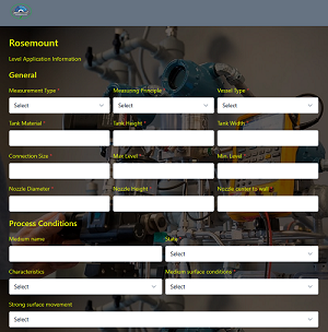
Note: There are several models, to choose the correct one for your aplication, please fill the form below
|