|
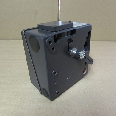
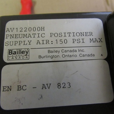
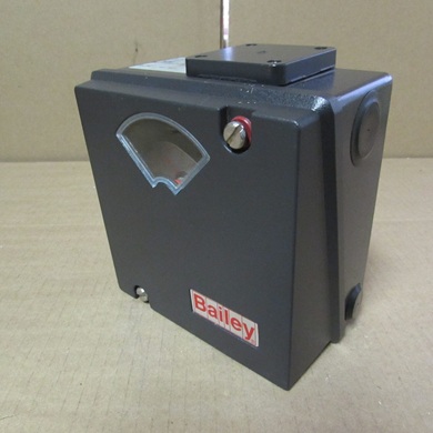
AV1 pneumatic and electro-pneumatic positioner AV1220000
The main difference is the input signal: AV1 pneumatic positioners use a pneumatic input, while AV2 electro-pneumatic positioners convert an electrical \(4\)-\(20\) mA signal into a pneumatic output. Both types work using a feedback loop to precisely position a pneumatic actuator by converting the input signal into a proportional pneumatic pressure. They operate via a force-balance principle where the mechanical feedback from the valve stem's position balances the force from the input signal.
AV1 pneumatic positioner
- Principle: Directly receives an external pneumatic signal to control the pneumatic output.
- Function: The input pressure is directly compared to the feedback from the valve's mechanical position.
- Operation: It uses a force-balance mechanism to adjust its pneumatic output to the actuator, ensuring the valve stem reaches the desired position dictated by the input signal.
AV2 electro-pneumatic positioner
- Principle: Receives an electrical control signal (e.g., \(4\)-\(20\) mA) from a controller.
- Function: An I/P converter (current-to-pneumatic) within the positioner converts the electrical signal into a proportional pneumatic pressure signal.
- Operation: This internal pneumatic signal is then used by the force-balance mechanism to control the pneumatic output to the actuator, just like the AV1, but the input starts as an electrical signal instead of a pneumatic one.
How both types work
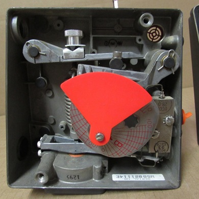
- Force-balance feedback: Both positioners use a mechanical linkage to connect the valve stem to a cam and lever assembly.
- Signal input: The input signal (pneumatic for AV1, electrical-to-pneumatic for AV2) creates a force on one side of the assembly.
- Actuator movement: The positioner directs pneumatic pressure to the actuator, causing the valve to move.
- Feedback loop: As the actuator moves, the mechanical linkage provides feedback, which applies a counter-force to the assembly.
- Position lock: When the feedback force balances the input force, the valve is at the correct position. The positioner then stops sending pressure to the actuator, maintaining that position until the input signal changes.
AV1 pneumatic positioner working principle
The AV1 pneumatic positioner receives a pneumatic pressure signal from an external controller and uses this signal to regulate the air pressure supplied to the actuator.
- Input signal: A pneumatic signal, typically 3–15 psig (0.2–1 bar), is applied to a diaphragm assembly.
- Force balance: The input signal pressure exerts an upward force on a diaphragm and a balance beam. This force is opposed by the tension from a range spring, which is connected to a feedback cam.
- Pilot valve operation:
- Increasing signal: As the input signal pressure increases, the diaphragm force overcomes the spring force, causing the balance beam to pivot. This movement operates a pilot valve, which increases the air pressure sent to the actuator.
- Decreasing signal: When the input signal decreases, the range spring's force becomes dominant, pivoting the balance beam in the opposite direction. This causes the pilot valve to vent air from the actuator.
- Feedback mechanism: The actuator's movement (either linear or rotary) rotates a cam via a mechanical linkage. The cam's movement changes the tension of the range spring. When the actuator reaches the position commanded by the input signal, the forces on the balance beam are equalized, and the pilot valve stops sending or exhausting air.
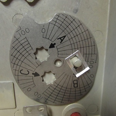
- Output characterization: The AV1 uses a specially shaped cam that allows for a variety of relationships (e.g., linear, square, square root) between the input signal and the final valve position.
AV1 electro-pneumatic (AV2) positioner working principle
The electro-pneumatic positioner, designated as the AV2 in the ABB product line, adds an I/P (current-to-pneumatic) converter to the AV1's pneumatic design. This converter translates an electrical control signal into the internal pneumatic signal that drives the force-balance mechanism.
- Input signal: The positioner receives a standard electrical current signal, typically 4–20 mA, from an electronic controller.
- I/P conversion: The 4–20 mA electrical signal is sent to an internal I/P converter. This converter uses the electrical current to create a proportional pneumatic signal, which is then fed into the same diaphragm assembly as the AV1 pneumatic model.
- Force balance: From this point, the process is identical to the pneumatic version. The converted pneumatic signal pressure acts on the diaphragm, balancing the force of the range spring.
- Pilot valve and feedback: The balance beam operates the pilot valve to supply or exhaust air to the actuator. The actuator's physical position is then fed back to the balance mechanism through the cam and range spring, ensuring the valve is accurately positioned according to the electrical input.
- Fail-safe action: On loss of the electrical input signal, the AV2 can be set to fail in a safe position (e.g., fully open or fully closed).
Summary of key differences
| Feature |
AV1 Pneumatic Positioner |
AV2 Electro-pneumatic Positioner |
| Input Signal |
Pneumatic (e.g., 3–15 psig) |
Electrical (e.g., 4–20 mA) |
| Signal Conversion |
No conversion necessary; directly uses the pneumatic input. |
Uses an internal I/P converter to transform the electrical signal into a pneumatic signal. |
| Hazardous Areas |
Can be used in hazardous areas as it does not require electricity. |
Specialized explosion-proof converters and housings are available for hazardous environments. |
| Fail-Safe |
Fails to a specific position (e.g., fails at 3 psig input). |
Fails to a specific position on loss of current signal. |
 full datasheet here full datasheet here
Positioner Transmitter Feature
- Manufacturer: AV1
- Product No. : AV1220000
- AV1 - Pneumatic positioner
- Input signal: 2 - 0.2 to 1.86 bar (3 to 27 psi), standard temperature range –40 to 82 °C (–40 to 180 °F)
- Stroke or rotary motion: 2 - 25.4 to 101.6 mm (1.0 to 4.0 in) or 90° rotation
- Manifold / gage block: 0 - No manifold
- Position transmitter: 0 - No position transmitter
- Drive shaft: 0 - Standard with drive arm (for linear actuators) and UP3 / 4 / 5 / 6
- Options: 0 - No options
There are several Model of electro-pneumatic positioner, for more details read the PDF below
Basic Ordering Information
|