|
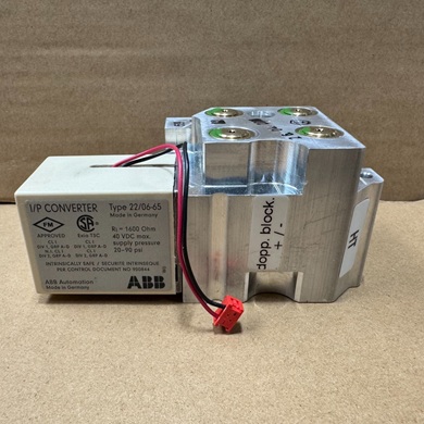
ABB I/P signal converter- 22-06-65 (4-20mA)
The ABB 22-06-65 is an I/P signal converter that converts a 4-20 mA electrical input signal to a 3-15 psi (0.2-1 bar) pneumatic output signal using a force-balancing principle. The device uses the electrical current to create a magnetic field that exerts a force on a lever arm, which is counteracted by the pneumatic pressure in a nozzle. This creates a balance of torques, and any imbalance causes the lever to rotate, adjusting the air gap at the nozzle to change the dynamic air pressure and ultimately produce the correct output signal.
Detailed working principle
- Input and force generation: The 4-20 mA electrical input flows through a coil, which generates a magnetic field. This field applies a force to a magnet on a lever arm.
- Force balancing: A counterforce is applied to the other side of the lever arm by the air pressure in a nozzle and flapper assembly. The converter is designed to achieve a balance between these two forces (torques).
- Feedback and adjustment: If the torques become unbalanced, the lever arm rotates, changing the air gap between the nozzle and the flapper. This change in the air gap alters the dynamic air pressure at the nozzle.
- Output signal creation: A steady supply of compressed air is provided to the nozzle through a throttle. The power stage of the converter takes the resulting dynamic air pressure and converts it into the 3-15 psi pneumatic output signal.
- Two-wire technology: The converter uses a two-wire loop, meaning the same wires supply power to the device and carry the output signal, simplifying wiring and allowing secondary devices like controllers or recorders to be connected in series.
Operating principle
The working principle of the 22/06-65, which is based on the broader TEIP11 I/P converter family, relies on the interaction between an electromagnetic force and a pneumatic force
- Electrical input and magnetic field: An electrical input signal (e.g., 4–20 mA) flows through a coil, which is positioned in a magnetic yoke. The coil generates an electromagnetic force that is directly proportional to the magnitude of the input current.
- Force balance: This electromagnetic force acts on one side of a lever arm. A counterforce is generated on the opposite side of the lever by a dynamic air pressure acting on a flapper and nozzle assembly.
- Pressure modulation: When the input current changes, it creates a force imbalance on the lever arm, causing it to rotate. This rotation changes the gap between the flapper and the nozzle. The nozzle is connected to a steady supply of air via a throttle.
- Pressure conversion: The change in the flapper-nozzle gap modifies the backpressure at the nozzle. This dynamic pressure is then sent to a power stage that converts it into the final pneumatic output signal, such as 3–15 psi.
- Achieving equilibrium: The system continuously adjusts the flapper position to maintain a balance of the two opposing forces. If the input current increases, the magnetic force pulls the lever, causing the output air pressure to rise until the pneumatic force on the flapper is once again in equilibrium with the magnetic force.
Key components and features
- Input: 4–20 mA electrical signal.
- Output: 3–15 psi pneumatic signal.
- Design: The 22/06-65 model is specifically designed for DIN rail mounting in a control room, with 1/8-inch NPT pneumatic connections.
- Volume booster: Some versions of the 22/06-65, such as the V18311H-612210100 model, include an internal volume booster. This allows the converter to drive pneumatic valves directly, eliminating the need for a separate booster.
- Intrinsically safe: Certain models, like the TEIP11-PS, are certified as intrinsically safe for use in hazardous areas.
 full datasheet here full datasheet here
|