|
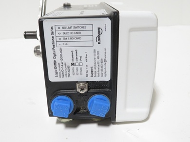
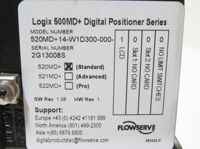
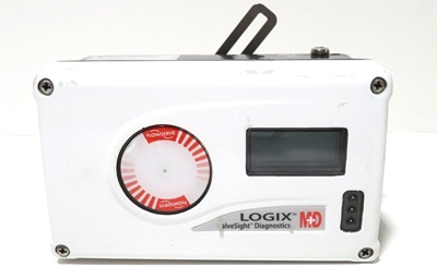
Flowserve Positioner Logix 500MD Series - 520MD-14-W1D300-000-1000
The Logix 500MD series works by using a two-wire, 4-20 mA input signal to control a valve actuator through a two-stage control loop. The 4-20 mA signal is processed by a microprocessor, which compares it to the measured valve stem position. The microprocessor then sends a signal to a pneumatic amplifier, which uses air pressure to move the actuator to the desired position, providing tight control.
Detailed working principle
- Input and initial processing: The system receives a 4-20 mA control signal, which is also used to power the entire circuit. A microprocessor reads this input and compares it to the current position of the valve stem.
- Pneumatic amplification: The microprocessor sends an output command to a piezo valve inside a pneumatic amplifier.
- The pneumatic amplifier controls the flow of air to the actuator, which is what causes the valve to stroke or move.
- The position of the pilot valve within the amplifier is fed back to a secondary control loop, which provides for more precise control than a single-stage system.
- Positioning and control: As the valve approaches its target position, the difference between the commanded and measured positions decreases.
- This causes the output to the piezo valve to decrease, slowing the movement as it gets closer.
- When the valve is at the desired position, the pneumatic amplifier's output is zero, which holds the valve steady.
Communication and diagnostics:
- The Logix 520MD and later models can use the HART protocol for two-way communication, allowing for remote monitoring, configuration, and diagnostics.
- Diagnostic software like ValveSight can detect potential issues and help perform tests like Partial Stroke Testing.
- An auto-tune function can be used to automatically set the control parameters for optimal performance.
Key components and their functions
- Microprocessor-based electronic control module: This component receives the 4–20 mA command signal from the process controller and determines the necessary adjustments to achieve the target valve position. For specific models like the 520MD, this module also enables two-way communication using the HART protocol.
- Piezo valve electro-pneumatic converter: The microprocessor sends a command to the internal piezo valve, which precisely controls the pilot pressure. This pilot pressure then drives a pneumatic amplifier.
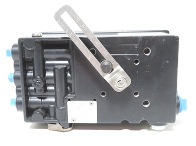
- Infinite resolution valve position sensor: A feedback sensor, typically a follower arm attached to the valve stem, provides continuous, highly accurate measurement of the valve's actual position. This signal is sent back to the microprocessor.
- Pneumatic amplifier: This component uses the pilot pressure from the piezo valve to control the flow of a larger volume of air to the valve actuator, causing the valve to move.
- Valve actuator: The actuator converts the air pressure changes from the pneumatic amplifier into the physical force and motion needed to operate the valve.
Step-by-step working principle
- Command signal input: The positioner receives a standard 4–20 mA analog signal from a control system, which represents the desired valve position (e.g., 4 mA is fully closed, 20 mA is fully open).
- Position comparison: The microprocessor inside the positioner compares the input command signal to the real-time position feedback from the valve position sensor.
- Error calculation and control: The microprocessor's control algorithm calculates the difference (error) between the commanded position and the actual position.
- Piezo valve activation: Based on the error calculation, the microprocessor sends a command to the piezo valve to increase or decrease the pilot pressure. The piezo valve, which has no moving parts and consumes very little power, can make very precise pressure adjustments.
- Pneumatic amplification: The pilot pressure from the piezo valve controls the pneumatic amplifier, which opens and closes internal poppet valves to regulate the main air supply to the actuator.
- Actuator movement: The regulated air pressure from the amplifier causes the actuator to stroke, moving the valve stem or shaft.
- Closed-loop feedback: As the valve moves, the position sensor continuously updates the microprocessor with its new position.
- Position stabilization: When the valve approaches the desired position, the error signal decreases. The positioner reduces the air pressure, slowing the actuator's movement until the actual and commanded positions match. The air output is then held at zero to maintain the valve in a constant position.
Advantages of this technology
- High precision: The digital control algorithm and infinite resolution position sensor provide extremely accurate positioning.
- Fast commissioning: Features like "Quick-Cal" and "Auto-Tune" allow for rapid and simple calibration, reducing setup time.
- Advanced diagnostics: For models with HART communication, the positioner provides extensive diagnostic data, including valve signatures, leak detection, and performance monitoring. This helps predict and prevent potential failures.
- Low air consumption: The piezo technology allows for high-performance control with minimal air use, improving efficiency.
- Reliability: The state-of-the-art technology and diagnostic capabilities lead to high reliability and uptime.
 Full Datasheet Full Datasheet
Positioner Transmitter Feature
- Manufacturer: Logix 500MD
- Product No. : 520MD-14-W1D300-000-1000
- 500MD - Intrinsically Safe, IP-66 / HART; 8-DIP Set-Up with LCD Option; Standard (Basic Functionality)
- Certifications: 14 - General Purpose
- Housing: W - Aluminum - Black Base with White Cover
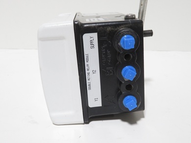
- Threaded Connections: 1 - Mounting: 5/16" 18 UNC, Pneumatics: 1/4" NPTF, Conduit: 1/2" NPTF, Vents 1/4" NPTF
- Feedback Shaft: D - D - 316 Stainless Steel Shaft (Valtek Standard)
- Action: 3 - Four-way (Double-Acting), Spool Style Relay
- Position Indicator: 0 - No Indicator
- Special Options: 0 - No special options
- Manifold: 00 - No Manifold
- Gauges: 0 - No Gauges
- Display: 1 - LCD
- Auxiliary Card Slot 1: 0- Slot 1 - No Card
- Auxiliary Card Slot 2: 0 - Slot 2 - No Card
- Limit Switches: 0 - No Switches
There are several Model of positioner, for more details read the PDF below
Basic Ordering Information
|