|
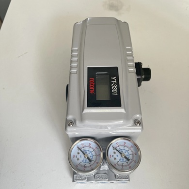
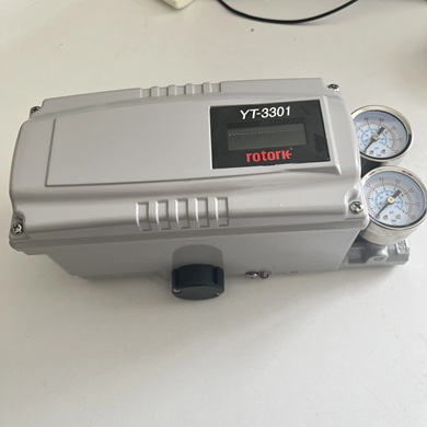
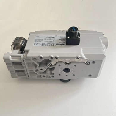
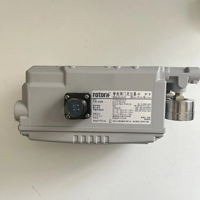
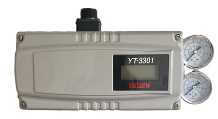
ROTORK /YCT YT-3301 Series - YT-3301LDI1221S1
The Rotork YT-3301 Smart Positioner works by receiving a \(4-20\) mA input signal from a controller and accurately controlling a valve's stroke to match that signal. A built-in microprocessor optimizes performance by enabling features like auto-calibration, PID control, and HART communication. The positioner uses a feedback mechanism to report the actual valve position and compares it to the command signal, making adjustments to minimize the difference.
Working principle
- Input Signal: The device receives a standard \(4-20\) mA electrical signal from a control system, which represents the desired valve position.
- Microprocessor: A built-in microprocessor interprets the input signal and controls the pneumatic output to the actuator.
- Pneumatic Control: The positioner sends air pressure to the actuator to open or close the valve. It controls the amount of air pressure to achieve the exact position commanded by the input signal.
- Feedback Loop: A feedback sensor (either built-in or a separated module) measures the actual position of the valve stem or shaft.
- Correction: The microprocessor compares the actual position to the commanded position. If there is a discrepancy, it will adjust the air pressure to the actuator to correct the valve's position.
- Unique Functions: The microprocessor allows for advanced features, including:
- Auto-calibration: The unit automatically calibrates itself for optimal performance.
- PID control: The positioner can perform its own proportional-integral-derivative (PID) control to manage valve position and reduce hunting.
- HART communication: The positioner communicates with the control system using the HART protocol for digital data and control.`Alarms: It can trigger alarms based on various conditions.
- User Interface: It includes an LCD display and buttons for local control and configuration, as well as a switch for manual operation.
Core components and their functions
- Microprocessor: The "brain" of the device. It processes the input signal, receives feedback on the current valve position, and calculates the necessary adjustment.
- Input signal: An electrical signal, typically 4-20 mA DC, is sent from a control system (DCS, PLC, etc.) and represents the desired valve position.
- Supply pressure: A constant source of clean, dry air is connected to the positioner to provide the pneumatic power needed to move the valve actuator.
- Electro-pneumatic transducer (I/P): A solenoid or torque motor converts the variable electrical current from the microprocessor into a corresponding, variable pneumatic signal.
- Pneumatic relay/valve assembly: This component receives the pneumatic signal from the transducer and controls the flow of the main supply air to the actuator. It is responsible for amplifying the pneumatic signal to deliver the force required to move the actuator.
- Position sensor (remote): The YT-3301 is a remote-type positioner, meaning the sensor is separate from the main body. This sensor continuously monitors the physical position (stroke or rotation) of the valve stem.
- Feedback signal: The position sensor sends a 4-20 mA electrical signal back to the positioner's microprocessor, representing the valve's actual position.
The closed-loop control process
- Desired position input: The positioner receives a 4-20 mA DC current signal from a control system, which tells it what position the valve is supposed to be in (e.g., 50% open).
- Actual position measurement: The remote sensor continuously measures the actual physical position of the valve stem and sends a feedback signal (typically a 4-20 mA output) to the positioner's microprocessor.
- Microprocessor comparison: The microprocessor compares the desired position from the input signal with the actual position reported by the sensor.
- Error signal calculation: If there is a difference between the desired and actual positions, the microprocessor calculates an "error" signal. This is a core function of the built-in PID (Proportional-Integral-Derivative) control algorithm.
- Pneumatic output adjustment: The microprocessor sends a new, precise control signal to the internal electro-pneumatic transducer.
- Actuator movement: The pneumatic relay receives the signal from the transducer and rapidly adjusts the air pressure being supplied to the actuator's diaphragm or pistons. This moves the valve stem or shaft.
- Correction and stabilization: The process repeats in real time. The microprocessor continues to monitor the actual position and adjust the pneumatic output until the actual position matches the desired position. This continuous feedback loop ensures high accuracy and stability.
Key features enhancing the working principle
- Auto-calibration: This function allows the positioner to automatically calibrate itself to the actuator's stroke range. The microprocessor maps the 4-20 mA signal to the physical travel limits, simplifying setup.
- HART communication: This protocol allows for digital communication over the analog 4-20 mA signal. Technicians can remotely configure settings, perform diagnostics, and get feedback from the positioner.
- Remote sensor (YT-3301): The YT-3301 model's remote sensor is designed to improve performance in harsh environments with high temperature or vibration by separating the sensitive electronics from the stress.
- Adjustable output characteristics: The positioner can be configured for different flow characteristics, such as linear, quick-opening, or equal percentage, to match specific application needs.
 Full Datasheet Full Datasheet
Positioner Transmitter Feature YT-3301LDI1221S1
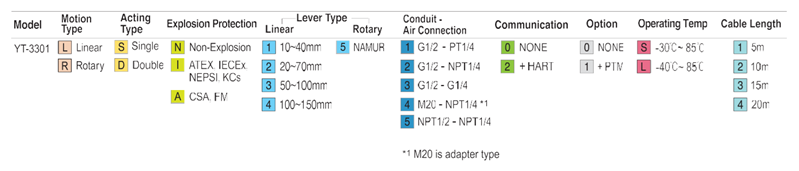
Basic Ordering Information
|