|
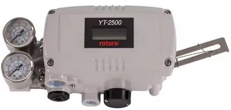
ROTORK /YCT YT-2500 Series - YT-2500RDN5201S
The YT-2500 smart valve positioner works by receiving a 4-20mA input signal from a controller to accurately control a valve's stroke. It uses a micro-processor to optimize performance, and features like PID control, auto calibration, and HART communication allow for precise and advanced operation. It also includes a fail-freeze function that holds the valve at its last position if the input signal or air pressure fails.
Key working principles
- Receiving and processing input: The positioner receives an electrical input signal (4-20mA) from a controller.
- Controlling the valve: This electrical signal is converted into pneumatic output to accurately move the valve stem to the correct position, as instructed by the controller.
- Micro-processing: A built-in microprocessor handles the processing of the input signal, optimizes performance, and manages other features.
- PID control: The device can perform proportional-integral-derivative (PID) control for more precise regulation of the valve's position.
- Auto-calibration: It can automatically calibrate itself to the valve's characteristics, simplifying setup and setup.
- HART communication: The HART protocol allows for two-way digital communication, enabling the user to monitor status and exchange data with the positioner and valve.
- Fail-freeze function: If the input signal or air supply fails, the positioner will lock the valve in its current position, which is crucial for safety and system stability.
- Feedback signal: It can send an analog feedback signal (4-20mA) back to the controller to report the valve's exact position.
Key operating principles
- Input signal: The positioner receives a standard electrical control signal, typically 4–20 mA, from a controller. This signal represents the desired valve position (the set point).
- Signal conversion and processing: The positioner's microprocessor processes the incoming electrical signal. A transducer then converts the electronic signal into a proportional pneumatic output pressure.
- Feedback loop: A feedback mechanism, either mechanical or electronic, is physically linked to the valve's stem or shaft. This provides a continuous real-time measurement of the valve's actual position.
- Comparison and error signal: The microprocessor acts as a control system within the positioner. It constantly compares the electrical input (desired position) with the feedback signal (actual position). Any difference between the two is an "error signal".
- Actuator control:
- To correct the error, the positioner adjusts the pneumatic pressure being sent to the actuator.
- If the valve needs to move further open, it increases the air pressure to the actuator.
- If the valve needs to close, it decreases the air pressure.
- Position stabilization: The positioner continues to adjust the air pressure until the feedback signal matches the input signal, at which point the valve stops moving and is held firmly in the correct position.
Smart capabilities
Unlike simpler positioners, the YT-2500's microprocessor gives it "smart" functionality, which includes:
- Auto-calibration: Automatically calibrates the zero and span settings for simplified setup.
- PID control: Allows for fine-tuning of the Proportional, Integral, and Derivative control parameters to minimize valve "hunting" (oscillation) and achieve optimal performance.
- HART communication: Supports the Highway Addressable Remote Transducer (HART) protocol, allowing for digital communication, remote monitoring, and diagnostics over the existing 4–20 mA signal line.
- Feedback signal: Outputs an analog feedback signal (e.g., 4–20 mA) that indicates the valve's current position to the control system.
- Fail-freeze function: A safety feature that locks the valve in its last position if there is a failure of the input signal or air supply.
 Full Datasheet Full Datasheet
Positioner Transmitter Feature YT-2500RDN5201S
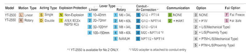
Basic Ordering Information
|


