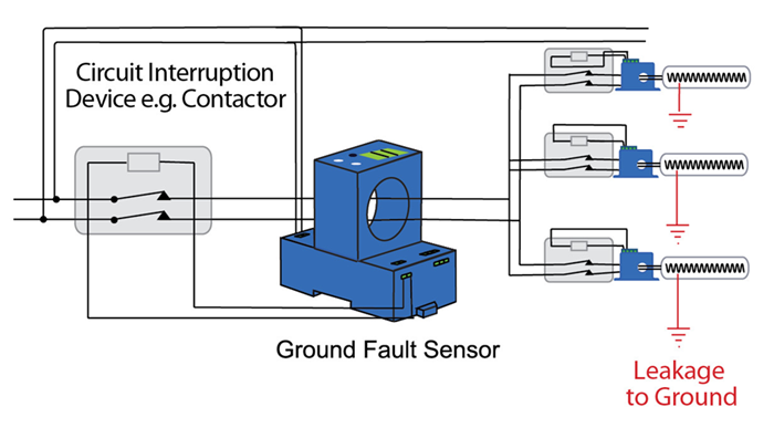
Earth/Ground Fault motor relay protection uses specialized relays to detect current leaking from a motor's phase conductor to its frame (ground), indicating insulation failure or damage, and quickly trips the circuit breaker to prevent equipment damage, electric shock, and fires, by monitoring zero-sequence current or voltage deviations and acting based on calculated settings for sensitivity and coordination. These relays provide critical safety and reliability, especially in systems with solid, resistance, or resonant grounding, using features like low-set (sensitive) and high-set (fast) stages, and can be time-delayed for selectivity.
How It Works
Detection: The relay continuously monitors the system for imbalances, typically measuring the sum of currents in the phases (zero-sequence current, (I0) or residual voltage, often using Current Transformers (CTs) or Voltage
Transformers (VTs).Fault Condition: Under normal operation, these sums are zero, but if a phase touches the motor casing or ground (due to insulation breakdown, moisture, etc.), current flows to earth, creating an
imbalance.Relay Action: When the leakage current or voltage exceeds the preset threshold (pickup setting), the relay initiates a trip
signal.Isolation: The signal opens the upstream circuit breaker, isolating the faulted motor from the power supply.
This video explains the basic principle of an earth fault relay:
Key Components & Settings
Zero-Sequence Current (I0): The primary measurement for many relays, representing the sum of phase
currents.Current Transformers (CTs): Used to measure the phase currents, often in a core-balance (residual)
arrangement.Low-Set Stage (I0>): Sensitive, definite or inverse time setting for detecting smaller faults, allowing coordination with downstream devices.
High-Set Stage (I0>>): Faster, definite time setting for clearing severe faults quickly.
Time Delay: Adjustable delay to prevent nuisance tripping from transient inrush currents and coordinate with other protection.
Watch this video to see how ground fault relay settings are calculated:
Types of Protection Schemes
Solidly Grounded: Short fault clearing times; sensitive monitoring.
Resistance Grounded: Limits fault current; allows for longer trip times.
Restricted Earth Fault (REF): Highly sensitive, used for internal transformer winding faults, using voltage (residual) or current.
Why It's Important
Safety: Protects personnel from electric shock.
Equipment Protection: Prevents catastrophic damage to motors, cables, and other connected equipment.
System Stability: Limits fault energy, preventing cascading failures and ensuring reliable power.
his video explains the importance of ground fault protection for 3-phase motors:
Earth/Ground fault motor relay protection is a critical safety system designed to detect unintended electrical paths between a motor's live conductors and the earth. These faults, often caused by insulation breakdown, moisture, or cable damage, account for approximately 98% of all electrical faults.
Core Operating Principles
Protection relays primarily use current sensing to identify imbalances between phase conductors.
Normal Operation: The vector sum of current in all three phases is zero (I1+I2+I3=0).Fault Condition: Current "leaks" to ground, causing a non-zero residual current. The relay detects this imbalance and sends a trip signal to the circuit breaker.
Primary Detection Methods
Method
Description
Best For
Residual Connection
Sums secondary currents of three phase-line CTs.
Standard LV systems; sensitivity typically >20% of motor rating.
Core Balance CT (CBCT)
A single toroidal CT encircles all phase conductors to directly sense zero-sequence current.
Measures current directly in the connection between transformer neutral and ground.
Large systems or when cable space limits CBCT use.
Voltage-Based (Neutral Shift)
Detects a rise in neutral-to-earth voltage using voltage transformers (VTs).
Insulated or high-resistance grounded systems where fault current is very low.
Specialized Protection Types
Restricted Earth Fault (REF): Provides zone-based protection for the motor or transformer windings specifically, ignoring through-faults outside the zone.
Directional Earth Fault: Uses the phase relationship between current and voltage to determine fault location; essential for systems with high capacitive charging currents (e.g., long cable runs).
Inverse Time vs. Instantaneous:
Instantaneous (ANSI 50G): Trips immediately for major faults.
Inverse Time (ANSI 51G): Delay decreases as fault current increases; useful for coordinating with downstream devices or handling starting inrush.
Key Challenges in Motor Protection
Starting Inrush: High starting currents can cause unequal CT saturation, leading to "false" residual current and nuisance tripping. Stabilizing resistors or time delays are often added to prevent this.
Variable Frequency Drives (VFDs): Harmonics and high-frequency switching can cause capacitive leakage that standard relays might misinterpret. Modern relays with digital filters are required for these applications.
Wound Rotor Motors: Ground faults in the rotor or DC excitation circuits are often "unseen" by standard stator-side relays.
Have a Questions?
+(39) 347 051 5328
Visit Our Company
Italy - Kazakhstan
Working Hours
09.00am to 18.00pm
About
We offer the best and economical solutions, backed by 27+ years of experience and international standards knowledge, echnological changes, and industrial systems.