|
Solid earthing (or grounding) Working Principle
Solid earthing (or grounding) works by directly connecting the neutral point of a generator or transformer to the earth using a conductor with negligible resistance and reactance. This creates a low-impedance path that keeps the neutral at earth potential, prevents transient overvoltages, and allows for rapid, high-magnitude fault current detection, which ensures swift protection device operation.
Key Working Principles and Characteristics
- Direct Connection: The neutral point is connected directly to the ground without any intentional insertion of impedance (resistors or reactors).
- Low-Resistance Path: The path offers minimal impedance, allowing a large, high-magnitude earth fault current (typically 25% to 100% of the three-phase fault current) to flow, which helps in quick isolation of the faulty circuit.
- Voltage Stabilization: The neutral point remains tied to the earth potential, which prevents the voltage of healthy phases from rising significantly during a single-line-to-ground fault.
- Fault Current Limitation: While the fault current is high, the system is designed to keep this current within safe limits for equipment.
Applications
- Commonly used in low-voltage distribution systems.
- Used in high-voltage systems, particularly above 220 kV.
- Ideal for systems where rapid clearing of ground faults is essential for safety.
The operating principle of solid (or "effective") earthing consists of directly connecting the neutral point of a three-phase system (such as a transformer or generator) to earth via a conductor with negligible impedance.
How It Works
- Potential Maintenance: The direct connection "locks" the neutral potential to ground (0 Volts) under all operating conditions.
- Fault Behavior: If a ground fault occurs on one phase, the voltage of the faulted phase drops to zero, while the voltages of the other two "healthy" phases relative to ground remain virtually unchanged (they do not exceed the normal phase voltage).
- Low Impedance Return Path: The system creates an easy path for the fault current to return to the source. This generates a high fault current, which is necessary to quickly trip protective devices such as circuit breakers or fuses.
Advantages and Disadvantages
| Advantages |
Disadvantages |
| Rapid Protection: High currents allow the relays to detect and isolate the fault instantly. |
Arc Damage: High current intensity can cause physical damage to components (e.g. burnt contacts). |
| Insulation Savings: Since the voltage does not increase on the healthy phases, the equipment can be isolated for phase voltage only. |
Instability: Severe electrical shocks during a fault can temporarily destabilize the grid. |
| Surge Control: Eliminates the risk of transient overvoltages due to electrical arcs. |
Interference: Strong fault currents can interfere with nearby communication lines. |
|
|
Common Applications
- Low-voltage (LV) systems: Widely used in residential and commercial environments (e.g., 400/230V systems) to ensure personal safety.
- High-voltage (HV) systems: Universally used for voltages above 33-123 kV where insulation costs become a critical factor.
Conclusion
The solid grounding of neutral point has the following advantages:
- The neutral is effectively held at earth potential.
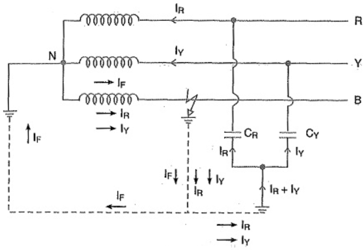
- When earth fault occurs on any phase, the resultant capacitive current IC is in phase opposition to the fault current IF. The two currents completely cancel each other. Therefore, no arcing ground or over-voltage conditions can occur. Consider a line to ground fault in line B as shown in Fig. above. The capacitive currents flowing in the healthy phases R and Y are IR and Iy respectively. The resultant capacitive current IC is the phasor sum of IR and Iy. In addition to these capacitive currents, the power source also supplies the fault current IF. This fault current will go from fault point to earth, then to neutral point N and back to the fault point through the faulty phase. The path of IC is capacitive and that of IF is inductive. The two currents are in phase opposition and completely cancel each other. Therefore, no arcing ground phenomenon or over-voltage conditions can occur.
- When there is an earth fault on any phase of the system, the phase to earth voltage of the faulty phase becomes zero. However, the phase to earth voltages of the remaining two healthy phases remain at normal phase voltage because the potential of the neutral is fixed at earth potential. This permits to insulate the equipment for phase voltage. Therefore, there is a saving in the cost of equipment.
- It becomes easier to protect the system from earth faults which frequently occur on the When there is an earth fault on any phase of the system, a large fault current flows between the fault point and the grounded neutral. This permits the easy operation of earth-fault relay.
Applications
Solid grounding is usually employed where the circuit impedance is sufficiently high so as to keep the earth fault current within safe limits. This system of grounding is used for voltages upto 33 kV with total power capacity not exceeding 5000 kVA.
Calculation
Low-reactance Grounding
ased on network constant ratios, the criteria to qualify as reactance grounded is:
Xₒ/X1 > 3
as seen at fault, but less than the value necessary for resonant grounding.
Inserting a low-reactance such that
Xₒ/X1 ≤ 3
at fault, is not reactance grounding.
When employing a solidly grounded grounding transformer, its reactance may be such that
Xₒ/X1 > 3
and the system is deemed reactance grounded.
Recommendations
It is not proper to endanger a generator winding with fault currents higher than the three-phase current at the terminals. In generators, the ground-fault currents are higher than the three-phase fault currents because the internal impedance seen by the ground-fault is less than the impedance to three-phase faults. The high current produces excessive heating and mechanical forces.
A suitable current limiting impedance, like a low-reactance reactor, should be installed in the neutral to avoid generator damage.
In transmission and distribution systems, without directly connected rotating machines, the neutrals of the transformers are usually effectively grounded and reactors are not typical.
The phase-to-ground fault current should range from 25% to 100% of the three-phase fault current. Less than 25% may cause damaging transient overvoltages. Choose the value of reactance needed to limit the ground-fault current to the preferred amount.
The ratio is
-
Xₒ/X1 = 10 when 25%
-
Xₒ/X1 = 1 when 100%
-
Xₒ/X1 = 3 when 60%
Limiting the ground-fault current to 60% of the three-phase fault current is the borderline between effective grounding and reactance grounding.
When installing a 100% reactor in a generator neutral, the system is not reactance grounded but effective grounded, by definition, and the maximum fault-current contribution of this generator to a line-to-ground fault anywhere in the system outside of the generator will be its three-phase fault current.
Low-resistance Grounding
In the USA, low-resistance grounding is the most popular method utilized to limit ground-fault current. The value of resistance is much lower than the high-resistance method and ranges from 5% to 20% of the three-phase fault current. Some applications limit the ground current to around 50A to 600A.
A typical resistor of 400A will allow enough current flow to operate the protective relays for fast fault clearing. These resistors are also time-rated. A standard figure is 10s because, like in effective grounding, the branch will shut down after the first ground-fault.
|


