|
UPS Rectification & Charging
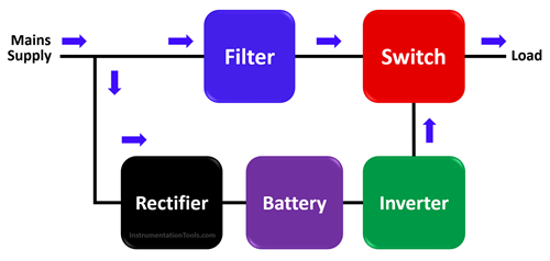
A UPS (Uninterruptible Power Supply) uses a rectifier to convert incoming AC utility power into DC to charge batteries and power the inverter, ensuring continuous power to equipment. When utility power is lost, the inverter instantly converts the stored battery DC power back into AC power.
Rectification & Charging Working Principle
- AC to DC Conversion: The rectifier takes the incoming 120V/230V Alternating Current (AC) from the grid and converts it into Direct Current (DC).
- Battery Charging: This DC power is used to continuously charge the connected battery bank, ensuring it is always ready to take over during an outage.
- Inverter Powering: The rectifier also provides DC power to the inverter, which converts it back to stable, clean AC to power the connected load, allowing for double conversion.
Key Components
UPS Operating Modes
- Normal Mode: Input AC is converted to DC by the rectifier (to charge the battery) and then to AC by the inverter to power the load.
- Battery Mode: During power failure, the battery provides DC to the inverter, maintaining the load.
In summary, the rectifier acts as the "input converter," charging batteries and feeding the inverter, while the inverter acts as the "output converter" for the load.
In an Uninterruptible Power Supply (UPS), the Rectification and Charging stage is the first critical step in ensuring continuous, clean power. Here is how this principle works:
- The Rectification Process
The UPS rectifier acts as a gateway that converts incoming Alternating Current (AC) from the utility grid into Direct Current (DC).
- Conversion: It uses power electronics (like diodes or thyristors) to "straighten" the AC wave into a steady DC flow.
- Conditioning: In many systems, this process also acts as an "electrical firewall," filtering out voltage spikes, noise, and frequency fluctuations from the grid.
- The Charging Principle
Once the power is converted to DC, it follows two parallel paths:
- Path A (Battery Charging): The rectifier/charger provides a regulated DC voltage to the battery bank to keep it at an optimal state of charge.
- Path B (Inverter Feed): Simultaneously, the DC power is routed to the Inverter, which converts it back to clean AC for your equipment.
- Transition During Outages
The beauty of this principle is seen during a power failure:
- Normal Mode: The rectifier powers the load and charges the battery.
- Outage Mode: The rectifier stops receiving AC. Because the batteries are already connected to the DC line, the Inverter immediately draws power from the stored energy in the batteries.
- Zero Transfer Time: In "Online" or "Double Conversion" systems, there is zero delay because the inverter is already running on the DC power provided by the rectifier.
Key Components Involved
| Component |
Function |
| Rectifier |
Converts AC to DC; filters incoming power noise. |
| Battery Charger |
Manages current to the batteries to prevent overcharging/damage. |
| Battery Bank |
Stores energy in DC form for emergency use. |
|


