|
UPS square Wave - Working Principle
A square wave UPS converts DC battery power to AC power by abruptly switching polarity, creating a, rough, block-shaped wave rather than a smooth sine wave. Utilizing an H-bridge circuit, it switches MOSFETs or IGBTs on and off to generate alternating positive and negative voltage pulses, ideal for simple, non-sensitive equipment at a low cost.
Key Working Principles
- Switching Mechanism (H-Bridge): The inverter uses four switches (transistors) in an "H-bridge" configuration. To produce alternating current (AC), switches (S1\S4) turn on to create positive voltage, then turn off while (S2\S3) turn on to create negative voltage.
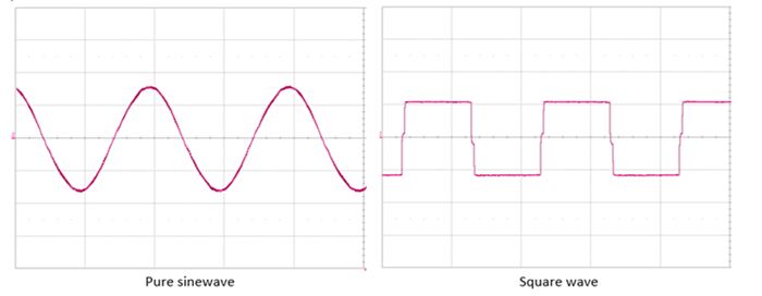
- Waveform Generation: Instead of a smooth, gradual increase and decrease in voltage, a square wave UPS jumps directly from maximum positive to maximum negative voltage, creating a "stepped" or jagged shape.
- Frequency Control: The switching speed is controlled by timing circuits to match the standard grid frequency (typically 50 Hz or 60 Hz).
- Battery Mode Operation: When a power outage occurs, the UPS battery supplies DC, which is immediately converted by this inverter circuit into a square wave AC output.
Characteristics
- Cost: It is the least expensive, simplest inverter design.
- Suitability: Best for devices with universal motors, simple tools, or lighting.
- Limitations: The non-smooth waveform can cause humming in audio equipment, overheating in motors, and may fail to power sensitive electronics with active PFC power supplies.
A square wave UPS (Uninterruptible Power Supply) operates by converting DC battery power into a basic, non-sinusoidal AC output characterized by sudden transitions between maximum positive and negative voltages.
Working Principle
The core mechanism is a process of electronic switching, typically utilizing an H-Bridge circuit:
- DC Input: When the main power fails, the UPS draws Direct Current (DC) from its internal battery.
- Electronic Switching: The UPS uses a set of switches (usually MOSFETs or IGBTs) arranged in an H-bridge configuration.
- Polarity Reversal:
- One pair of switches turns "on" to send current through the load in one direction for half a cycle (e.g., 8.33ms for 60Hz).
- The first pair turns "off," and a second pair turns "on" to reverse the current flow for the next half-cycle.
- Resulting Waveform: This rapid switching creates a waveform that jumps instantaneously between peak positive and peak negative values, remaining at each state for exactly half the cycle. This results in the characteristic block-like or "square" shape.
Key Characteristics & Limitations
- Harmonic Distortion: Square waves contain high levels of odd harmonics (multiples of the base frequency), which can cause buzzing noises or overheating in sensitive electronics.
- Device Compatibility: While fine for simple resistive loads (like light bulbs or heaters) and some universal motors, they may damage Active PFC power supplies commonly found in modern high-end PCs.
- Cost vs. Performance: This is the simplest and least expensive inverter design because it requires no complex filtering or pulse-width modulation (PWM) to smooth the wave.
|


