|
Construction and Design Criteria of MCC BusBars
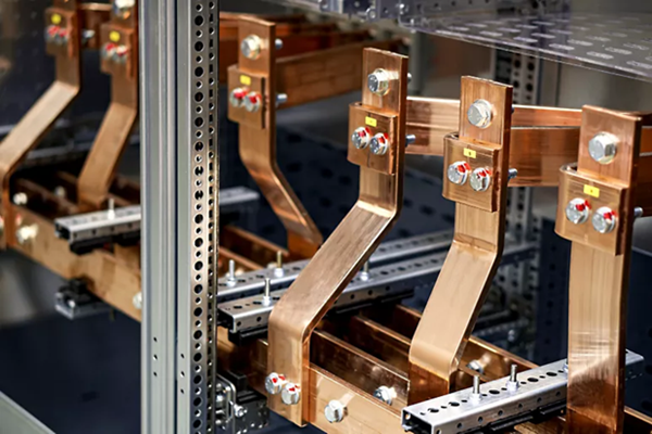
A bus bar is a thick, conductive metal strip (copper or aluminum) that acts as a central, low-impedance node to collect, conduct, and distribute high-amperage electricity from incoming sources to multiple outgoing loads. It operates on the principle of passive conduction, ensuring a consistent, high-capacity, and orderly distribution of power with minimal voltage drop
Key Working Principles
- Centralized Distribution: It acts as a common junction point—a "backbone"—where multiple incoming feeders gather, and multiple outgoing feeders distribute power.
- High-Capacity Conduction: Because of their large cross-sectional area, bus bars handle significantly higher current levels compared to conventional cables, reducing resistance, heat generation, and voltage sag.
- Voltage Uniformity: A bus bar maintains the same electric potential along its entire length, allowing multiple loads to draw power without impacting each other.
- Heat Dissipation: Often uninsulated and mounted on insulators, they allow for efficient cooling through natural convection, which is crucial for handling large, continuous currents.
- Modular Connections: Equipment such as transformers, circuit breakers, and feeders are bolted or clamped directly to the bar, making it easy to manage complex connections.
Types of BusBar Systems
- Single Busbar: Simple and cost-effective, but maintenance requires shutting down the entire system.
- Ring Main System: Forms a closed loop, ensuring power is not interrupted even if one section faults, as there are two paths for the current.
- Double Busbar: Offers high flexibility and reliability, allowing for maintenance on one bar while the other continues to operate.
Applications
Busbars are essential components in:
- Electrical switchboards and switchgear
- Industrial, commercial, and residential distribution boards
- Power substations
- Battery packs for EVs and renewable energy systems
- Renewable Energy Systems
- Industrial Machinery
- Electronic Devices
Types of Busbars
Suppliers have developed a wide variety of busbar types to meet the needs of a growing number of applications. Busbars can be grouped by the following characteristics:
- Material
- Suppliers manufacture busbars from any conducting material, but most use copper or aluminum. Copper metal has the second highest conductivity, after silver. Aluminum is the fourth-most conductive metal, but it is lighter and less expensive than copper. Both aluminum and copper bars are usually electroplated with coatings of tin, nickel, or silver to reduce corrosion and improve overall performance.
- Shape
The shape of busbars impacts their conductivity due to skin effect and the heat transfer from the bar. In most cases, the goal is to have a high ratio of surface area to cross-sectional area.
Here is a list of the most common shapes:
- Rigid busbar (flat bar): The most commonly used shape is a long, thin, rigid bar. They are often shaped at the time of manufacture to fit specific needs.
- Special cross-section busbars: Some busbars use “U,” “T,” or “L” shape cross sections to provide greater bending stiffness, increase surface area, and provide more connecting options.
- Laminated or flexible busbars: Flexible busbars are created by laminating thin metallic strips or foil. Not only does this make the busbars more flexible, but it also increases the total surface area and, therefore, conductivity.
- Round busbar: Busbars with a solid or hollow cylindrical cross section are used for high-current applications in which greater rigidity, rotation, or installation flexibility are needed.
- Insulation: Another way to distinguish a type of busbar is through how it is insulated from the surrounding structure. In some cases, it is coated with an insulating polymer, or it may be insulated and held in place by insulated mounts or isolators.
- Current-carrying Capacity and Type
A single-phase busbar has two circuits: one that is live and another that is neutral. Three-phase busbars use four conductors, one for each phase and another as a neutral run. Where single- and three-phase types deal with alternating current (AC) applications, some busbars carry direct current (DC).
The Advantages of Busbars
Engineers choose busbars for many reasons, usually due to cost, performance, and safety. In most cases, the following characteristics drive the choice of busbars over other power distribution options:
- Simplified power distribution: Busbars combine many electrical connections into a central hub. This is easier to design and maintain than complex wiring.
- Geometric flexibility: Busbars can be constructed into almost any shape and fit to almost any application.
- Connection ease: Busbars don’t need complex electrical connections. If power is needed, all you have to do is connect a wire to the surface.
- Form factor: The thin topology of busbars helps distribute power in tight spaces, as can be seen in battery packs, electronics, or industrial machinery.
- Rigidity: The structural stiffness of busbars eliminates the need for cable management. They can contribute to the structure's overall strength and bridge longer distances.
- Cost efficiency: Busbars can cost less than wiring options. They are also less expensive to install, maintain, and repair.
- Sustainability: Since they are made mostly of solid copper or aluminum, busbars are easy to recycle.
Simulation-driven Busbar Design
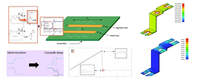
As can be seen by the different types of busbars, engineers have lots of choices in material, configuration, coatings, and geometry. Multiphysics simulation tools are a perfect complement to the design process because they provide a fast and accurate way to understand the interaction of electromagnetic fields, heat generation, heat transfer, and structural response.
Engineers want to optimize their busbar designs to have maximum efficiency, operate safely, and minimize cost. Once they understand what the routing of the circuit is, they can create a low-frequency
electromagnetic model. In general, it is possible calculate the electromagnetic field, heat generation, and losses due to resistance, capacitance, and inductance. They can optimize the geometry automatically or engage in what-if studies to determine the best shape for each module in their busbar. For more details, see the figure below as an example, created with the program simulator.
|


