|
Ring Main System Busbar - working principle
A Ring Main System (RMS) busbar operates by forming a closed-loop (ring) configuration, where electricity flows from the source in two directions to feed multiple distribution nodes. Each load connects to the ring via a Ring Main Unit (RMU) containing switches, allowing any node to receive power from either side if a section fails, ensuring high reliability and continuous supply
Key Working Principles
- Closed-Loop Supply: Power enters the ring via incoming cables and feeds out through multiple outgoing cables. If one side of the ring is broken (faulty), the load continues to receive power from the opposite side.
- Segmented Busbars: The ring is physically made of separate, linked busbar segments inside RMUs, enabling easy isolation of sections.
- Switching Mechanism: RMUs utilize load-break switches (LBS) for normal operation and fuses to break short-circuit currents, often enclosed in SF6 gas for arc quenching.
- Fault Management: If a fault occurs, only the specific section between switches is affected; the rest of the ring remains functional, providing high availability.
- Maintenance Flexibility: The design allows maintenance of a circuit breaker or transformer without interrupting power to other parts of the ring.
This system is commonly used in medium-voltage (MV) distribution, especially in urban areas or industrial sites where supply reliability is paramount
Working Principle
The core principle is bidirectional power flow, allowing electricity to reach any load point from two different directions.
- Loop Configuration: The main busbar sections are arranged in a ring, with circuit breakers or load-break switches placed between each section.
- Redundant Supply: Because the bus forms a continuous loop, if one section of the busbar or a feeder cable fails, that specific section can be isolated using its adjacent switches.
- Uninterrupted Service: While the faulty section is being repaired, power is automatically (or manually) rerouted from the opposite side of the ring, keeping the remaining loads energized.
- Sectionalization: Distribution transformers (Tee-offs) are tapped from the ring between two switching devices, ensuring they can be fed from either the "left" or "right" trunk.
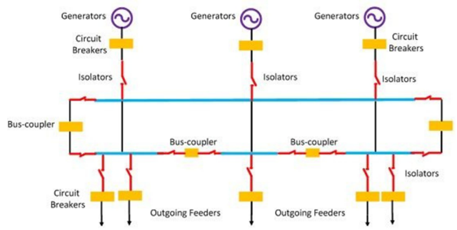
For more details see Figure below
Key Components & Functions
| Component |
Primary Role in the Ring System |
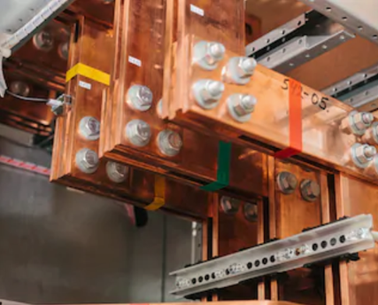
| Busbars |
High-conductivity metallic strips (copper or aluminum) that serve as the main highway for power. |
| Load Break Switches |
Used for normal operational switching and rerouting current during maintenance. |
| Circuit Breakers / Fuses |
Automatically disconnect a faulty section to prevent damage to the wider network. |
| Isolators |
Provide a visible break in the circuit for safety during manual maintenance. |
Summary of Benefits
- Reliability: High continuity of supply since a single feeder fault does not shut down the whole system.
- Voltage Stability: Reduced voltage fluctuations due to the sharing of loads between two parallel paths.
- Efficiency: Requires less conductor material than parallel radial feeders for a similar level of reliability.
|


