Double Busbar System - Working Principle

double1 bus

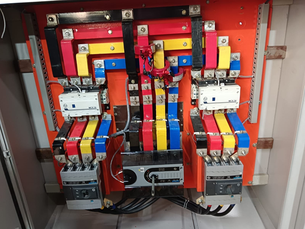
 A Double Busbar System consists of two independent busbars (main and spare/auxiliary), with each feeder connected to both via isolators and a single common circuit breaker. It ensures high reliability by allowing loads to be transferred between buses via a bus coupler for maintenance or in case of a fault without interrupting power.

Key Working Principles and Features

  • Structure: Two sets of busbars are provided. Each outgoing/incoming line is connected to both busbars through two independent isolators.
  • Bus Coupler: A, bus coupler circuit breaker and associated isolators connect the two busbars, enabling safe transfer of loads.
  • Normal Operation: Typically, all circuits are connected to the main busbar while the second busbar acts as a standby or "spare".
  • Flexibility & Maintenance: If the main busbar requires maintenance or fails, the load can be transferred to the standby busbar without shutting down the substation.
  • Load Transfer Process: To transfer a circuit from Bus A to Bus B:
  1. Close the bus coupler breaker.
  2. Close the isolator for Bus B on the feeder.
  3. Open the isolator for Bus A on the feeder.
  • Application: Commonly used in high-voltage (>33 kV) and critical substations to enhance power availability. 

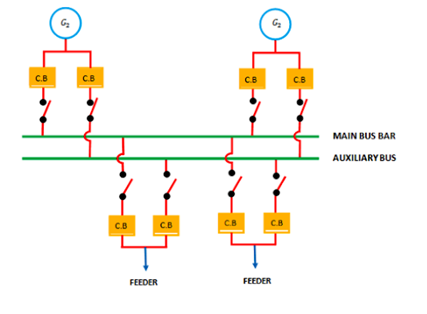
Working Principle

The system allows any incoming or outgoing circuit (feeder) to be connected to either busbar via a set of isolators (disconnecting switches).
  1. Normal Operation: Typically, all circuits are connected to the Main Bus, while the Reserve Bus remains energized but carries no load.
  2. Load Distribution: To balance the system or manage different power sources, feeders can be divided into two groups, each powered by a different busbar.
  3. On-Load Transfer: Using a Bus Coupler (a dedicated bay with a circuit breaker and isolators), loads can be transferred from one bus to the other without interrupting the power supply.
  4. Maintenance & Faults: If the Main Bus requires maintenance or suffers a fault, the entire substation load can be transferred to the Reserve Bus, ensuring service continuity.

For more details see Figure below

double bus

Key Components

  • Busbars (Main & Reserve): Two separate conductive sets, each capable of handling the full substation load.
  • Isolators: Switches that manually connect each feeder to Bus 1 or Bus 2.
  • Bus Coupler: A bridge between the two buses that "couples" them electrically during transfers to ensure they are at the same potential.

Typical Transfer Sequence (without power interruption)

To move a feeder from Bus I to Bus II:
  1. Close the Bus Coupler circuit breaker to synchronize the two buses.
  2. Close the isolator connecting the feeder to Bus II (the feeder is now temporarily connected to both).
  3. Open the isolator connecting the feeder to Bus I.
  4. Open the Bus Coupler circuit breaker.

Applications

This system is primarily used in high-voltage substations (often 33kV and above) where downtime is critical, such as in large industrial plants or major grid nodes.

Advantages

  • High Reliability: Continued operation during faults or maintenance.
  • Flexibility: Easy to reconfigure load distribution.

Disadvantages

  • High Cost: Requires double the equipment (isolators, busbars).
  • Complexity: Complex switching operations can lead to human error


favicon bacd

+(39) 347 051 5328

Italy - Kazakhstan

09.00am to 18.00pm

About

We offer the best and economical solutions, backed by 27+ years of experience and international standards knowledge, echnological changes, and industrial systems.

Marketing Materials

Spring Renovation
Industry
US Gas Company
Construct
Plus Project
Vam Drilling Service
X Project
X Project
Cabrrus Training

Marketing Materials1

Spring Renovation
Industry
US Gas Company
Construct
Plus Project
Vam Drilling Service
ultrasonic sensor
ultrasonic sensor
Cabrrus Training