|
Centralized Distribution Busbar System - Working Principle
A centralized distribution busbar system uses rigid conducting bars (copper or aluminum) as a common, central junction point to collect power from a main source and distribute it to multiple outgoing circuits. It works by feeding electricity into the busbar, which then supplies various loads through tap-off units along its length, providing high efficiency, flexibility, and easy maintenance compared to traditional cabling.
Key Working Principles
- Centralized Power Collection: Incoming power from a transformer is connected to the main busbar, acting as a high-capacity hub.
- Distribution via Tap-off Points: The busbar system allows for multiple outlets (tap-off units) to be plugged directly into the busbar at various points, facilitating easy connection of electrical loads (machines, panel boards).
- Reduced Complexity: Unlike point-to-point wiring, a single busbar system manages multiple feeders, simplifying the installation and reducing space requirements.
- Load Management: The system handles high-voltage loads and distributes power efficiently using insulated conductors.
- Protection & Safety: It incorporates circuit breakers at incoming and outgoing points to isolate faults, with the ability to add or remove loads (tap-off units) often while the system is live, improving operational uptime.
- The Core Working Principle
The system functions as a central node or junction point where incoming power (from a transformer or generator) is collected and then distributed to multiple outgoing circuits.
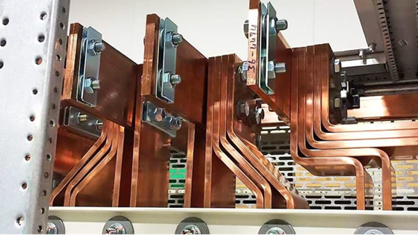
- Power Collection: Large metallic bars (typically copper or aluminum) receive electrical current at a single entry point.
- Parallel Distribution: The busbar maintains a constant electrical potential (voltage) along its entire length. Multiple "tap-off" units can then be plugged in at various points to draw power for different loads (e.g., machinery, server racks, or floor units).
- Modular Tapping: Unlike cables, which require a direct run from a distribution board to a load, busbars allow for "plug-and-play" connections without needing to shut down the entire system in many industrial designs.
- Technical Mechanisms
- Low Impedance: Due to their large cross-sectional area, busbars offer significantly lower electrical resistance than standard cables, which minimizes voltage drops and power loss during transmission.
- Thermal Management: The flat, broad shape of a busbar provides a high surface-area-to-volume ratio, allowing heat generated by current flow (I2R losses) to dissipate more efficiently via natural convection or radiation.
- Electromagnetic Efficiency: In three-phase systems, busbars are often arranged in a "sandwich" configuration to reduce inductive reactance and neutralize electromagnetic fields.
- Protection & Control
In a centralized protection scheme, the system utilizes a single central relay to monitor the entire busbar zone.
- Differential Protection: The central unit continuously compares the sum of incoming currents against outgoing currents. If they do not match, it identifies a "fault" within the busbar zone and instantly triggers circuit breakers to isolate the affected section.
- Smart Monitoring: Modern systems often integrate fiber-optic or wireless sensors to track temperature in real-time, preventing fires caused by loose bolted joints or overloading.
Key Benefits over Traditional Cabling
| Feature |
Busbar System |
Traditional Cable |
| Space |
Highly compact; saves up to 50% more space |
Bulky; requires large cable trays |
| Flexibility |
Modular; add/move loads anywhere |
Rigid; requires new cable runs for upgrades |
| Safety |
Enclosed in steel/aluminum for fire resistance |
Potential for "tangled" wires and insulation damage |
| Installation |
Enclosed in steel/aluminum for fire resistance |
Labor-intensive pulling and terminating |
|


